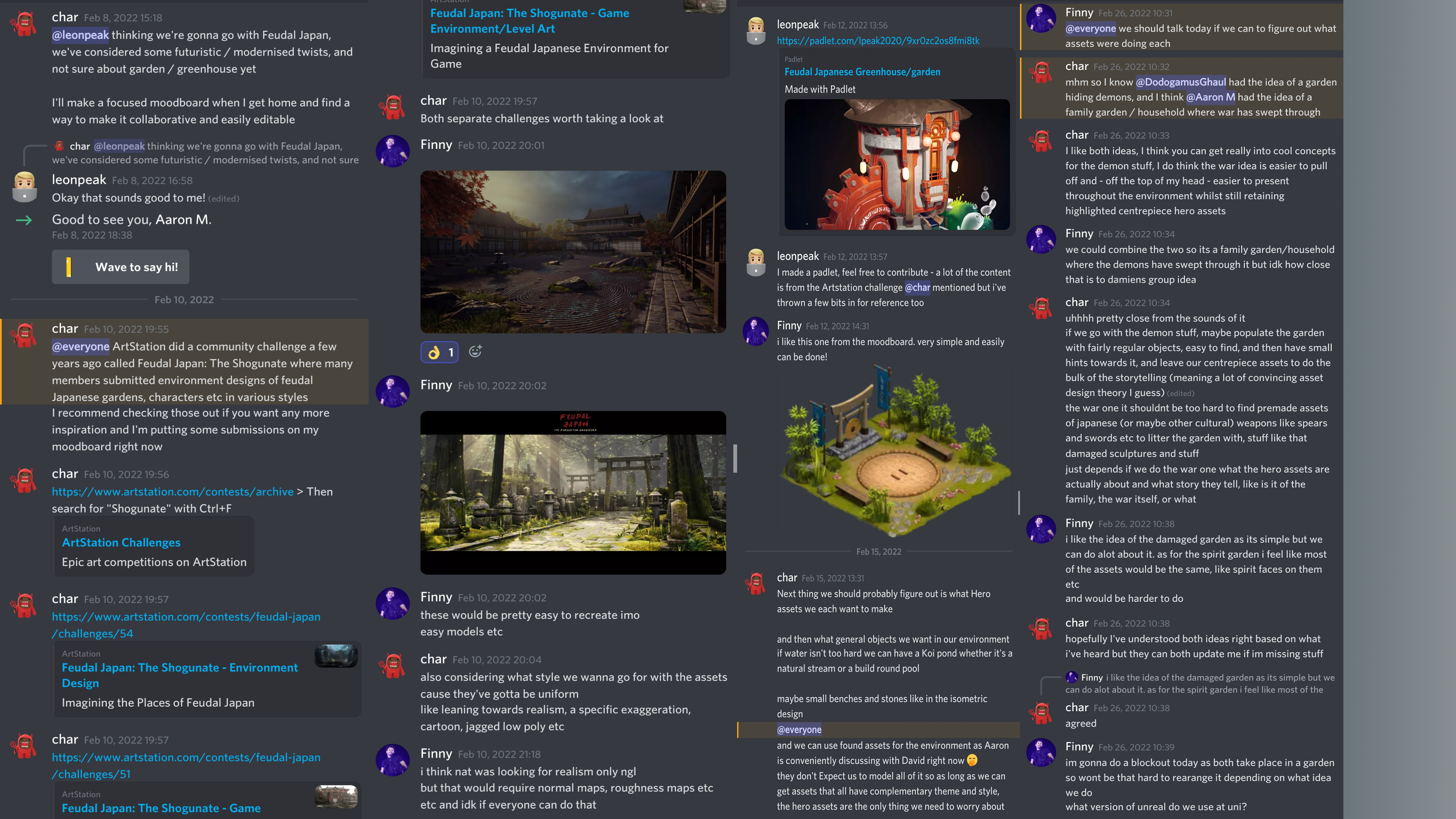
Planning and Research
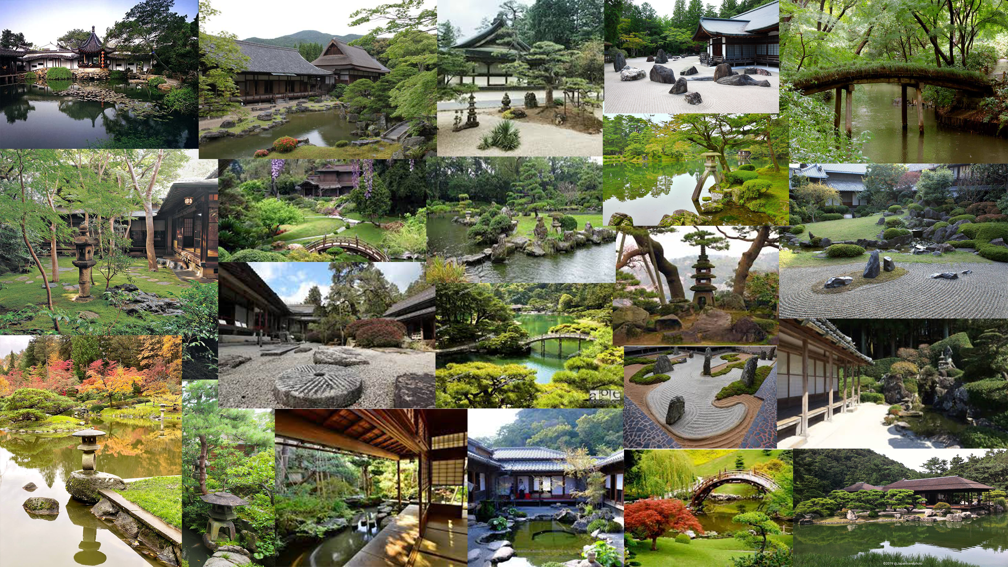
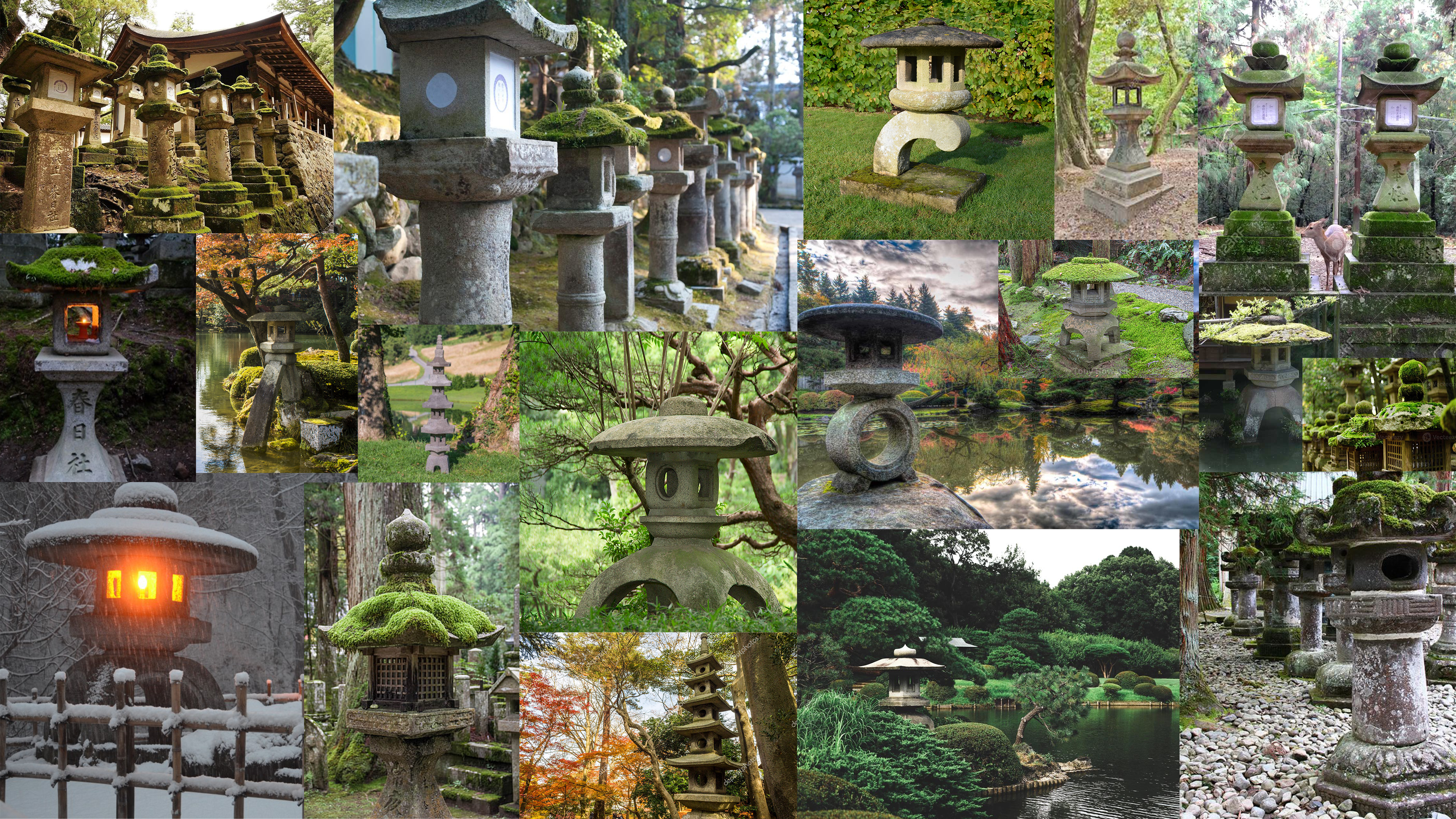
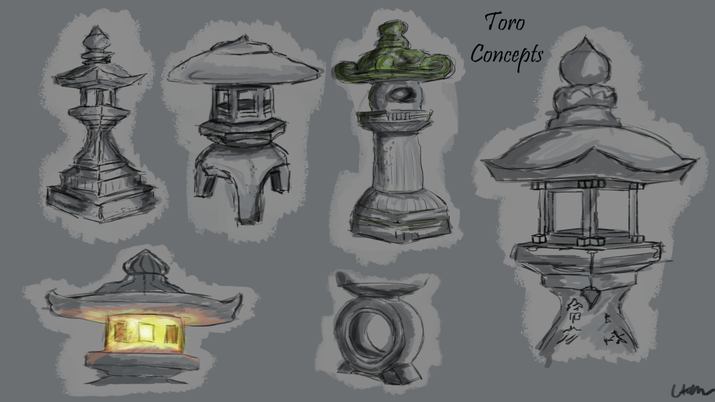
The location of the project was set as a garden, as a team we decided upon feudal Japan. We then spent some time researching images showing various Japanese gardens and their key assets of interest. From here we each decided which asset we would like to model and each respectively chose something we felt we could tell a story through. I have chosen a Japanese Toro lantern as my hero asset as after creating a mood board of ideas, I could see clearly there were different shapes, sizes and materials which gave a great scope for creativity.
Design exploration and rationale
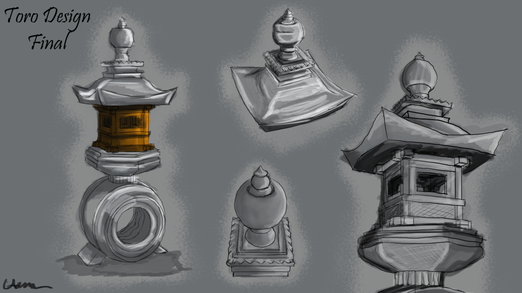
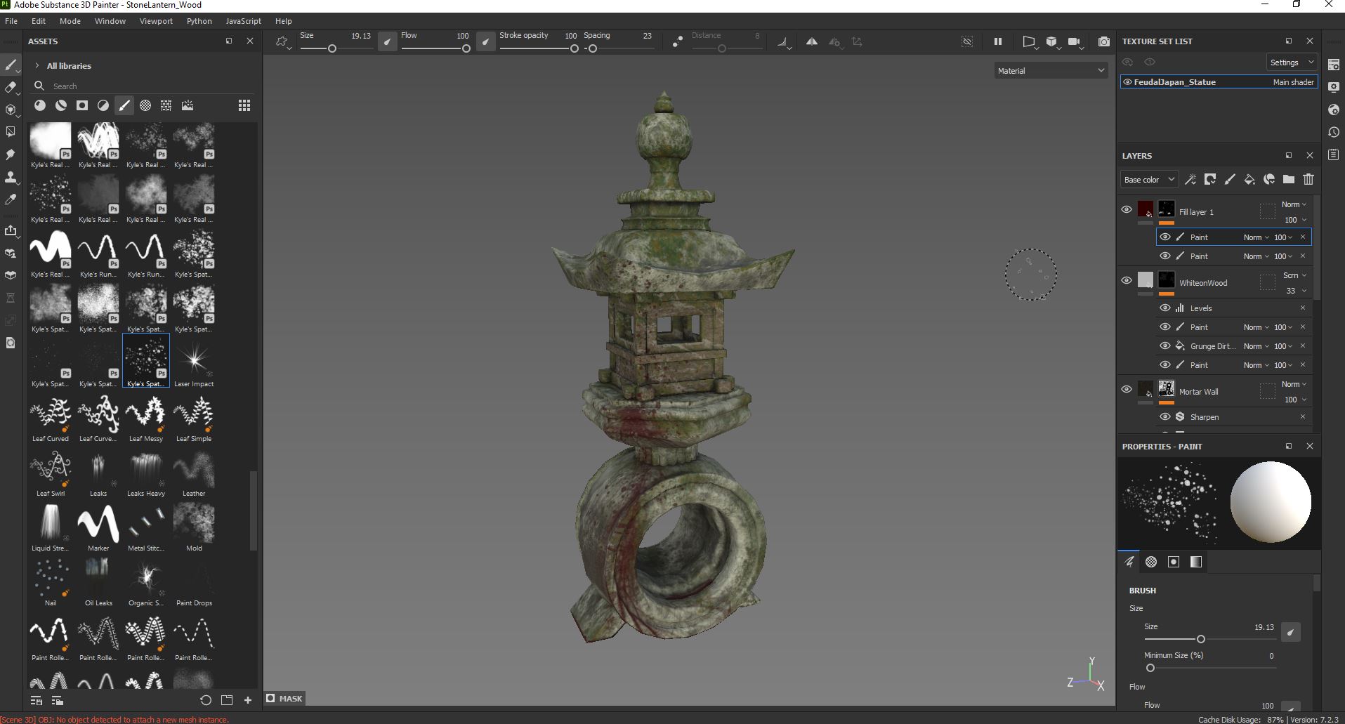
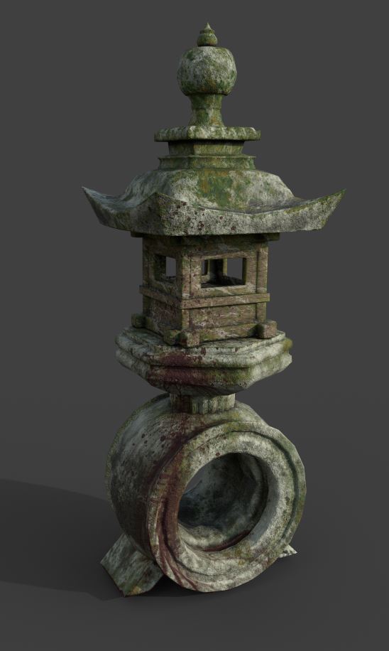
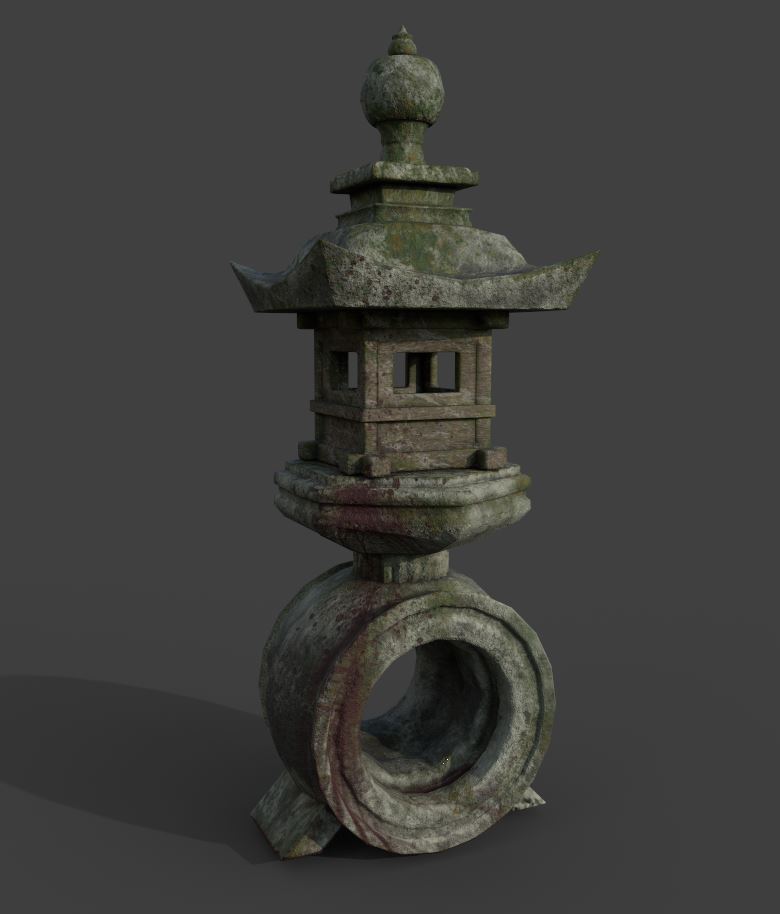
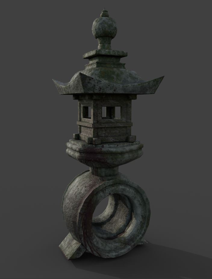
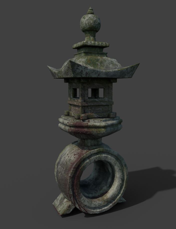
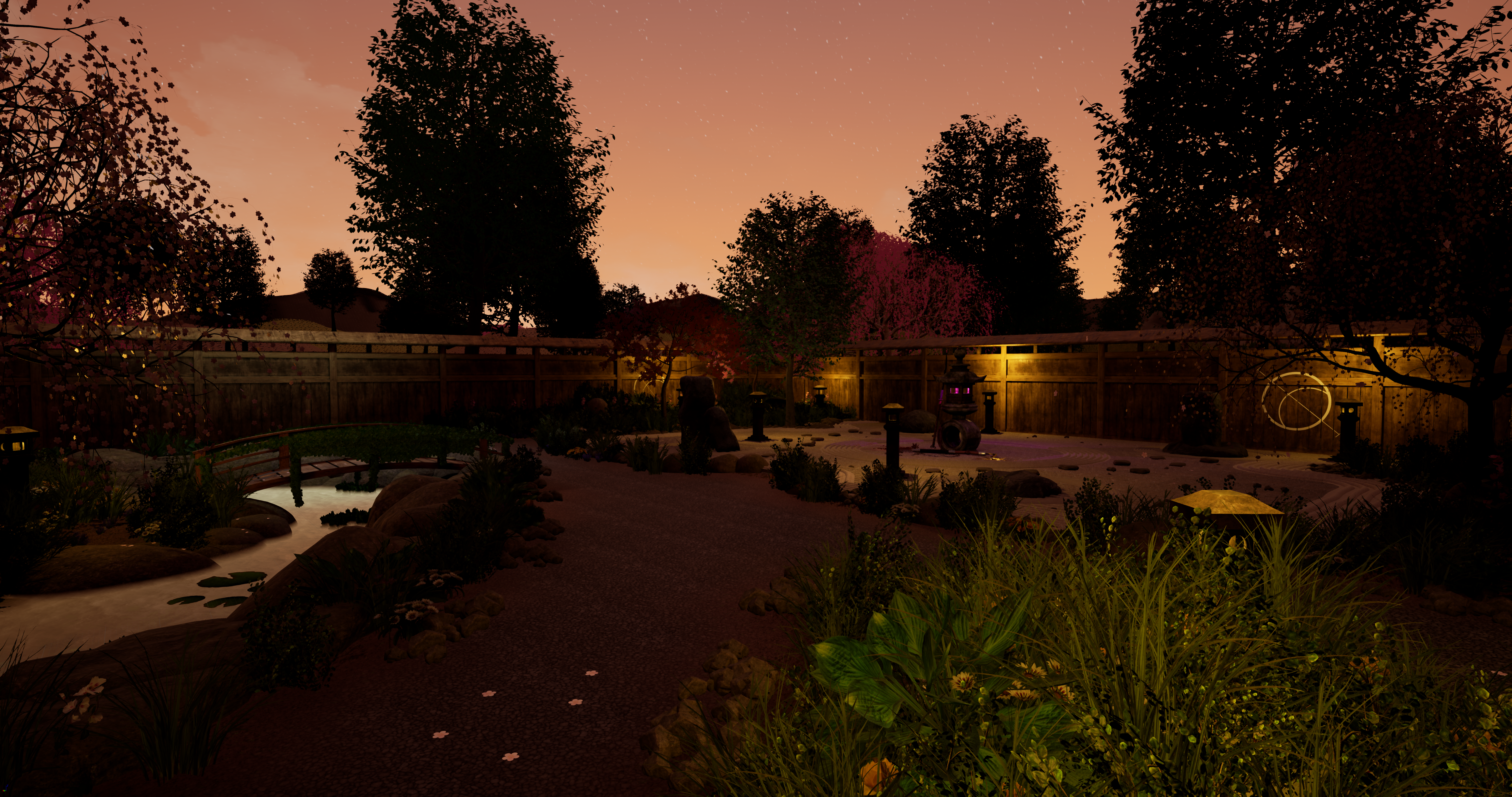
I have decided that a more decedent lantern featuring more shapes, patterns and materials makes for a more visually pleasing design. I added moss, lichen, dirt, and various other wear effects to achieve a stone lantern that looks like it has been stood in the elements for a long time. The blood on the lantern is part of the story that my team decided upon for the garden theme, it is to display the fact that a battle or death has taken place near to the lantern. The shapes used within the asset are of a stereotypical Japanese architecture using sharp geometric shapes, complex patterns and traditional inspiration. This demonstrates the use of form and function as this statue is used for a source of tranquility as well as a light source. As traditional Japanese lanterns are made from wood or stone, I textured the asset to make it look as realistic and rustic as possible.
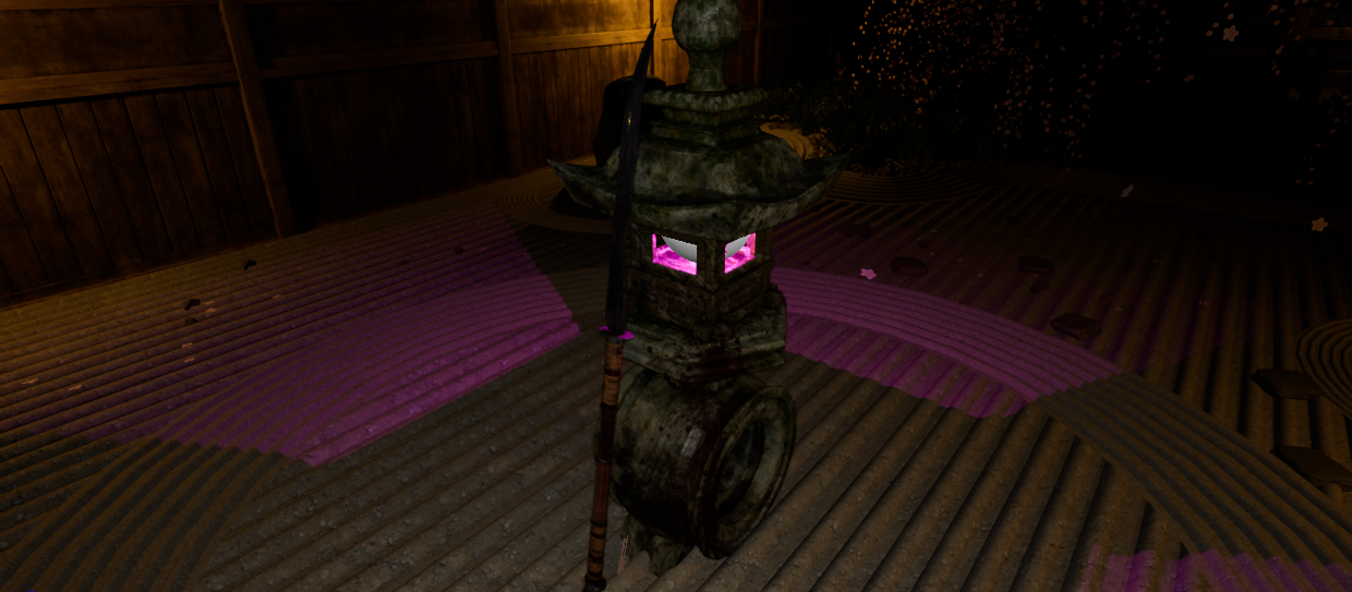
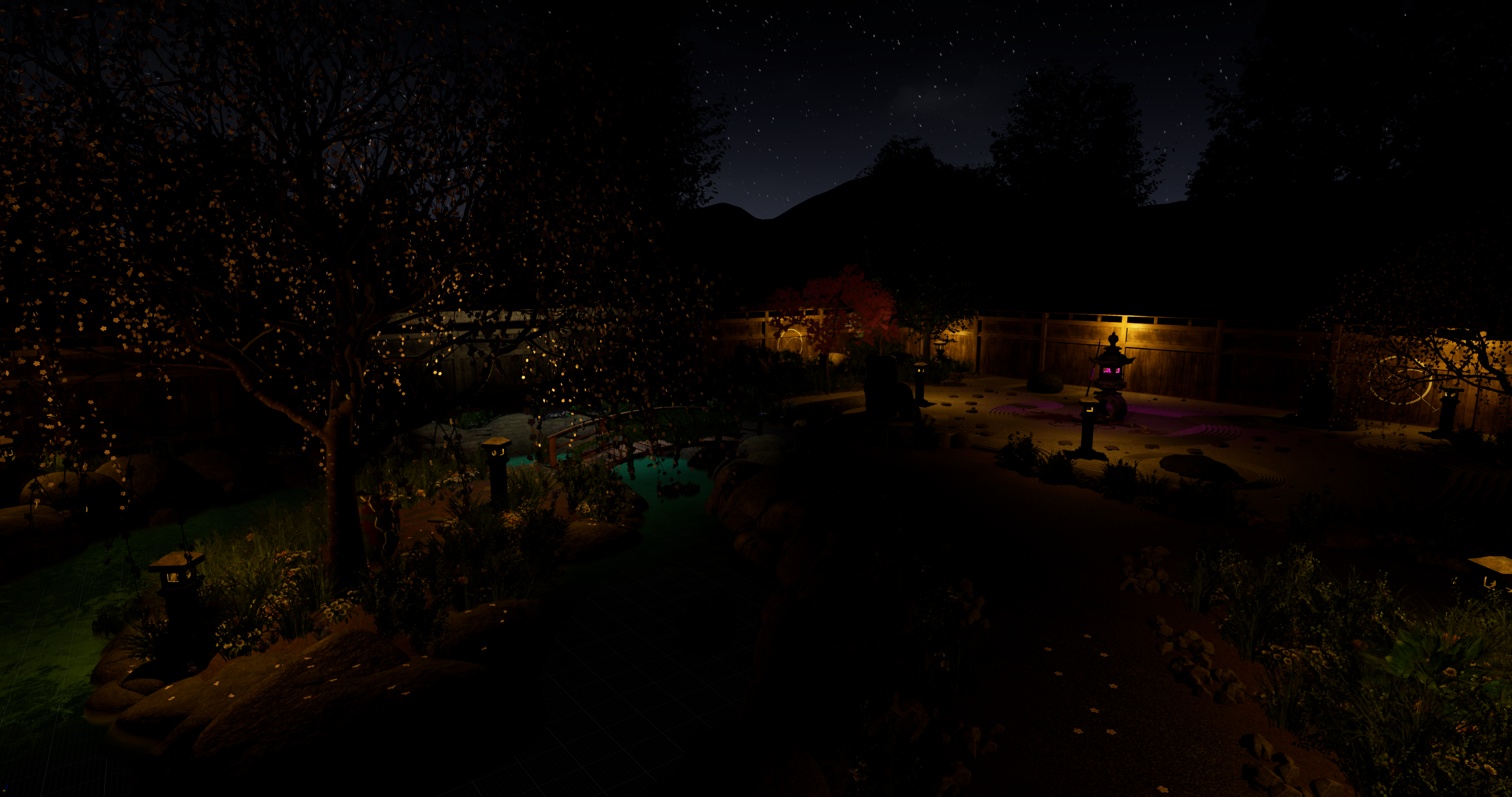
The Toro lantern was introduced to Japan from China during the 6th Century. As the story for our garden included the theme of rival clan, rampaging through a families’ house, in search of a cursed vase, I decided that within Unreal I would give the lantern a mystic and ominous glow instead of the natural light. As the scene is set in the night, I believe this curious glow would intrigue and draw the player in towards the asset. They would then immediately see once near the Toro, that a battle has taken place, through the extra weapon assets I have created.
Modelling and texturing (technical process)
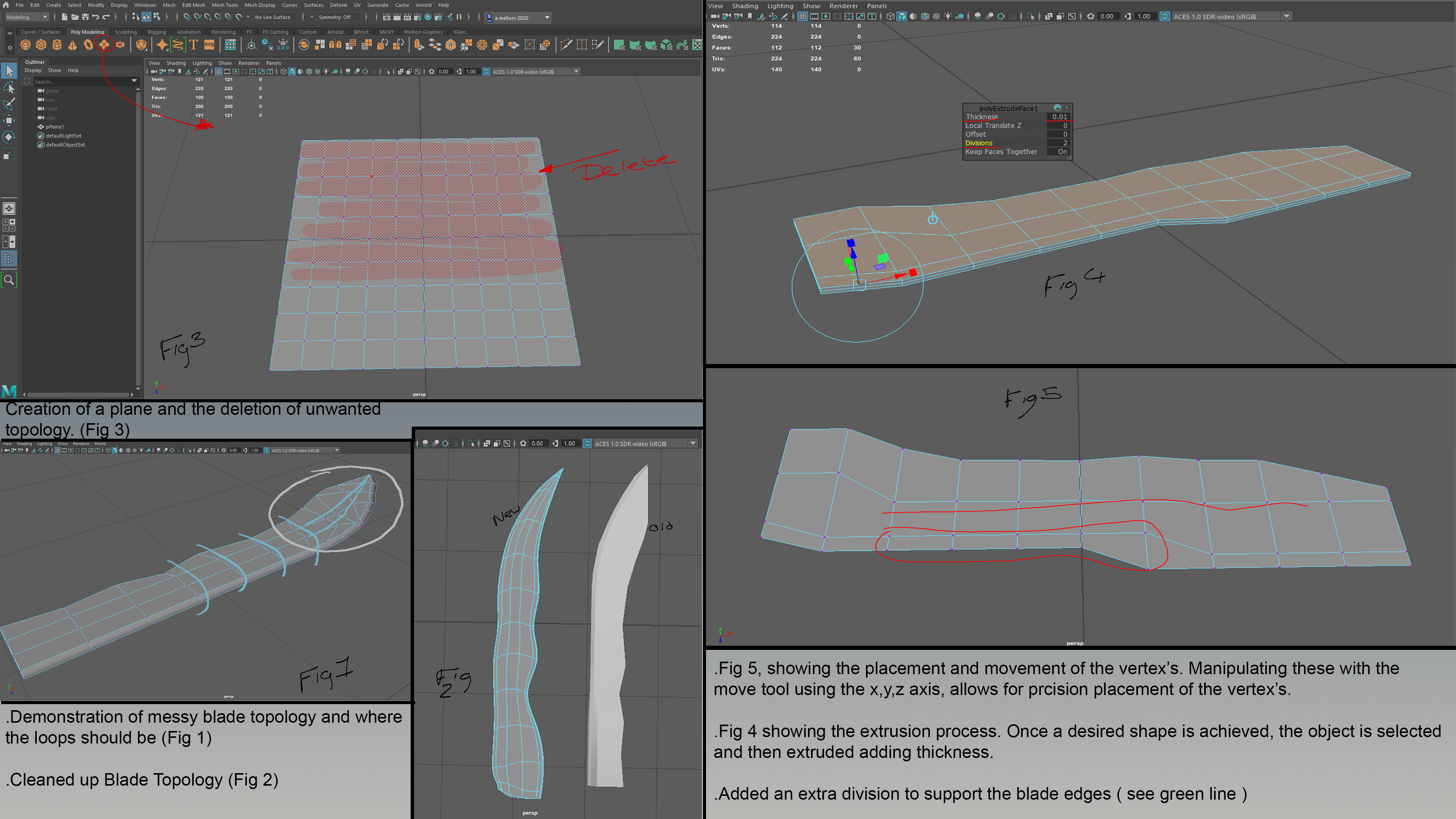
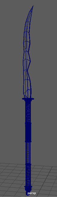
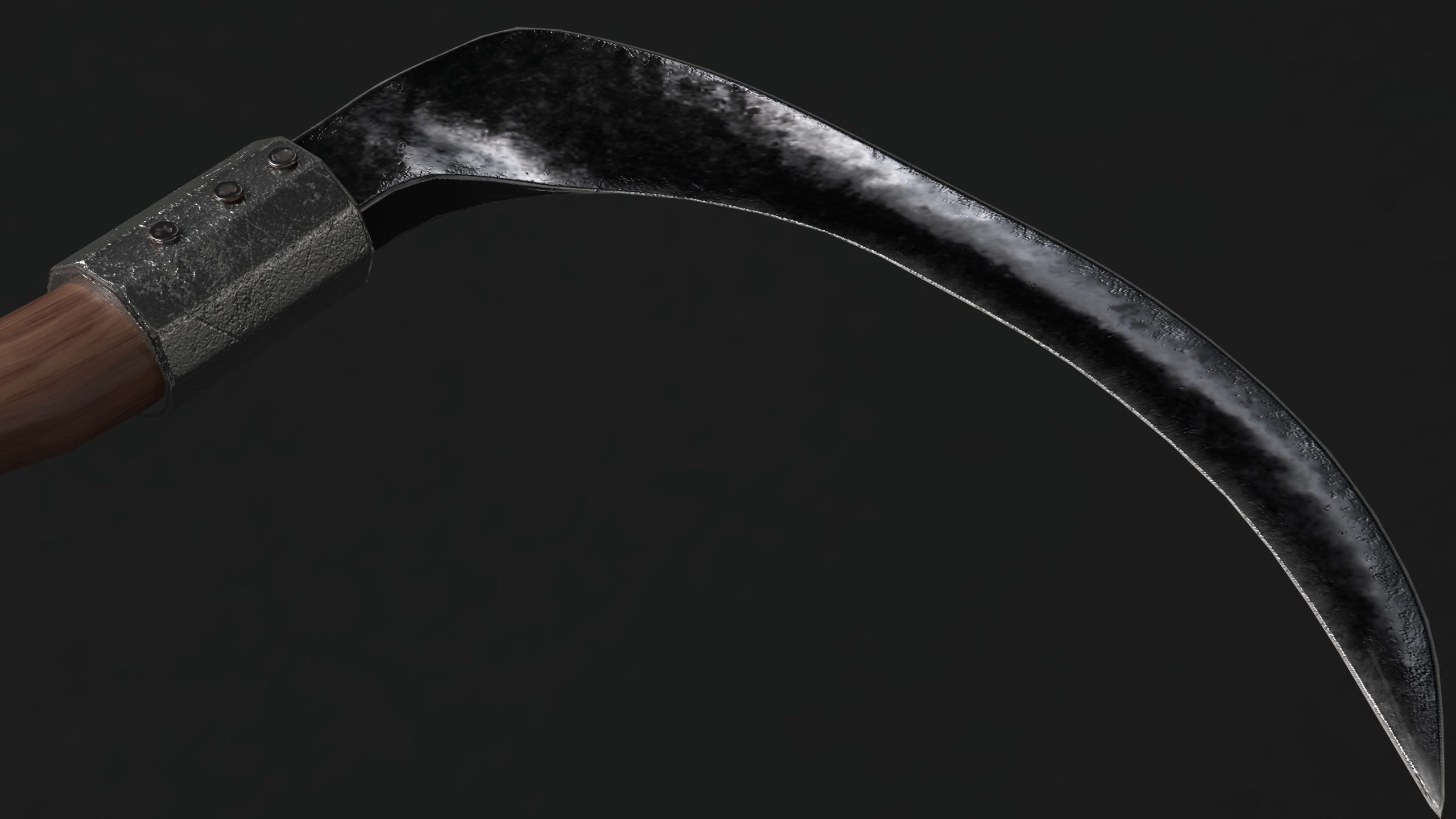
Fig. 1 shows a demonstration of a messy blade topology and where the loops should be. Fig. 2 shows the cleared-up blade topology. In Fig. 5 you can see the placement of the vertexes. By manipulating these with the move tool, using x, y, z axis, allows for precision placement of the vertexes. Fig. 4 shows the extrusion process. Once the desired shape is achieved, the object is then selected and then extruded to add thickness. I added an extra division to support the blade edges (see green line.)
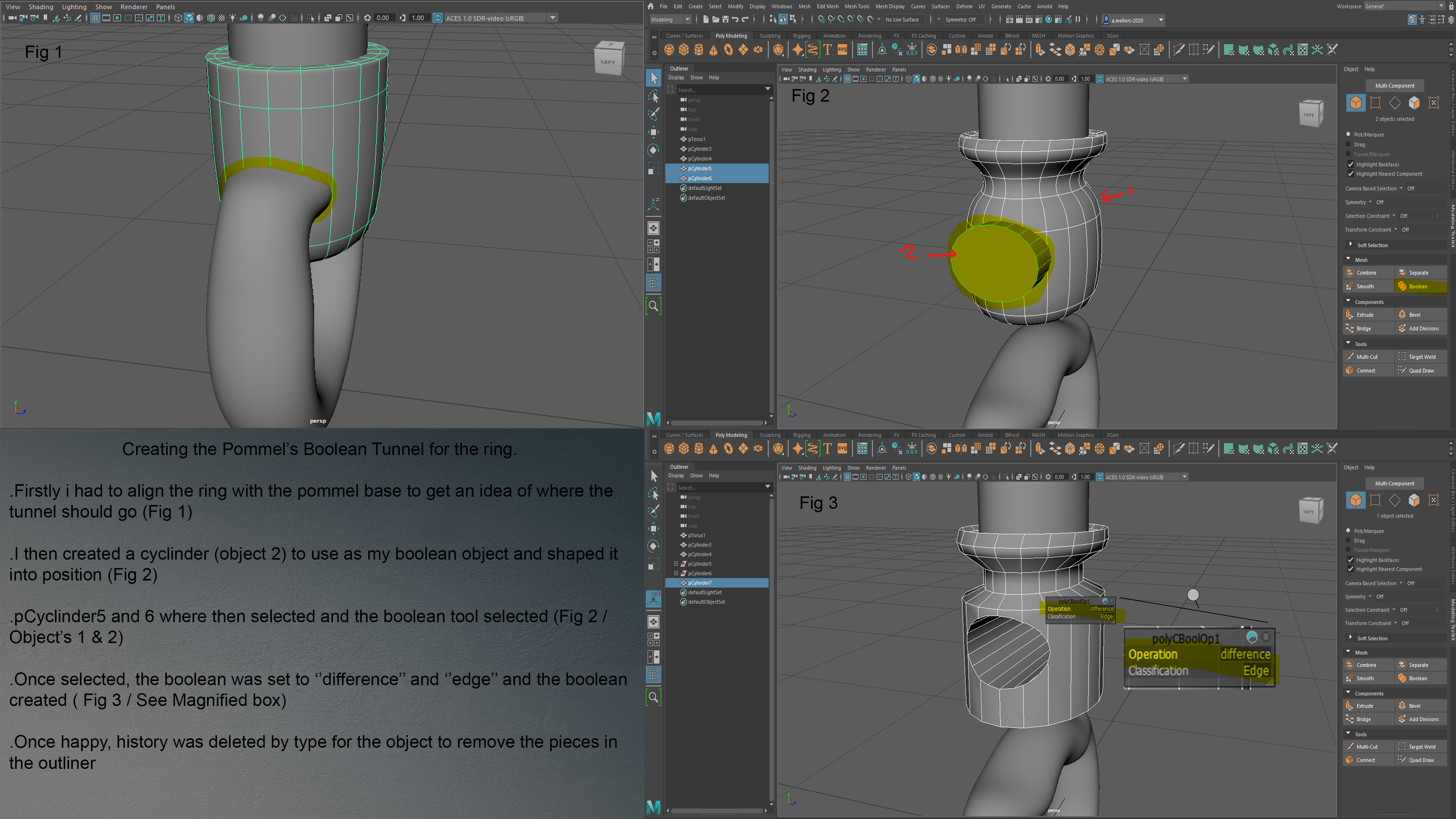
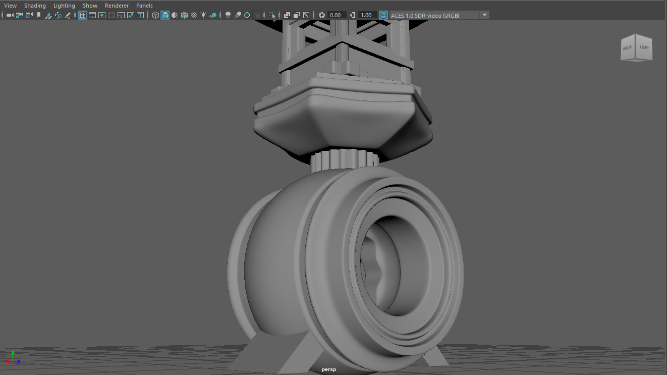
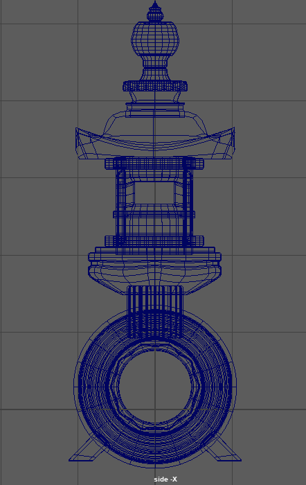
I had to align the ring with the pommel base to get an idea of where the tunnel should go. I then created a cylinder to use as my boolean object, then shaped it into position. Cylinders five and six were then selected and the boolean tool selected. The boolean was set to ‘difference’ and ‘edge’ and the boolean then created. Once I was happy with the design, the history was deleted by type for the object to remove the pieces in the outliner.
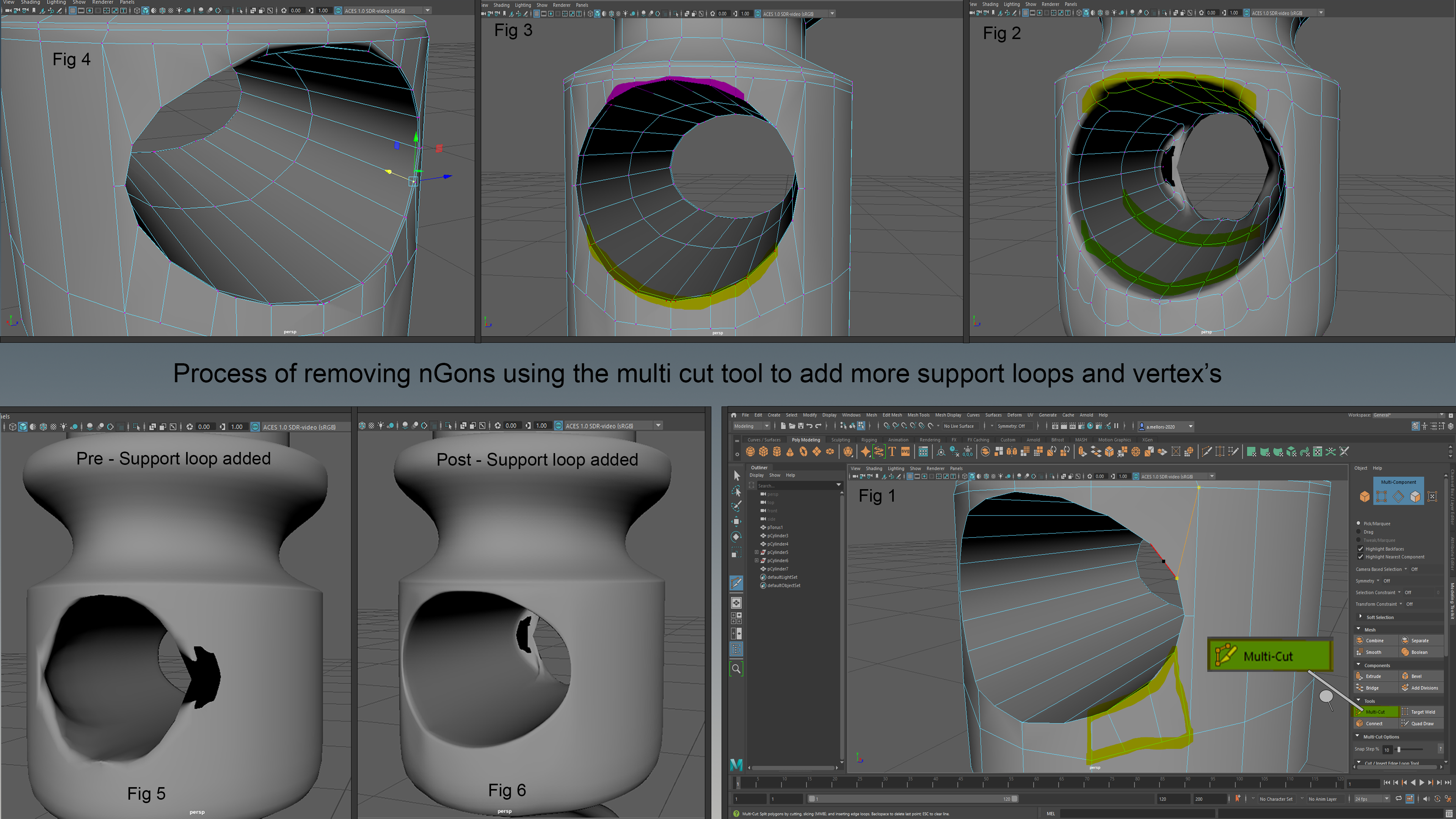
The image above shows the process of removing nGons using the multi cut tool to add more support loops and vertexes. After the boolean was performed, there was a lot of messy geometry and nGons. I had to manually go into the object and connect and add vertexes, until they all formed polygons. This can be seen in the image
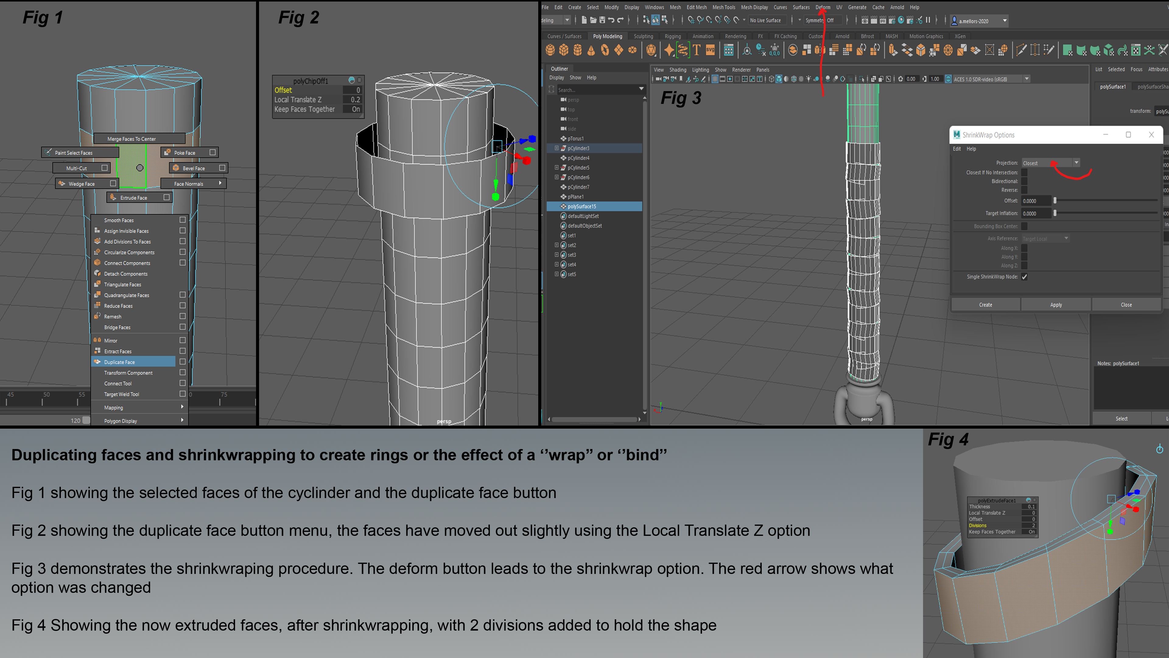
In the image above, I have duplicated faces and used shrink wrapping to create rings or the effect to ‘wrap’ or ‘bind.’ Fig. 1 shows the faces of the cylinder and the duplicate face button. Fig. 2 then shows the duplicate face button menus, the faces have been moved out slightly using the Locate Translate Z option. Fig. 3 then demonstrates the shrink-wrapping process. The deform button leads to the shrink wrap option. The red arrow shows which option was changed. Fig. 4 is showing the now extruded faces, after shrink wrapping, with two divisions added to hold the shape.
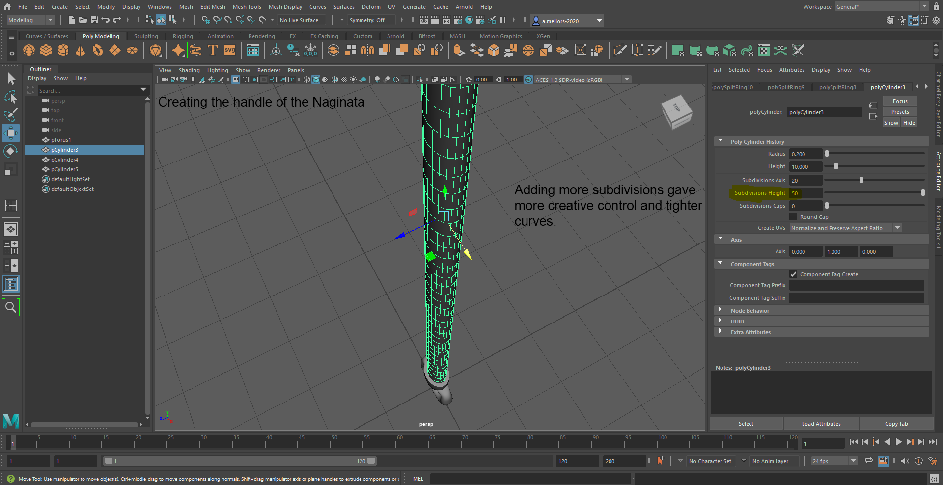
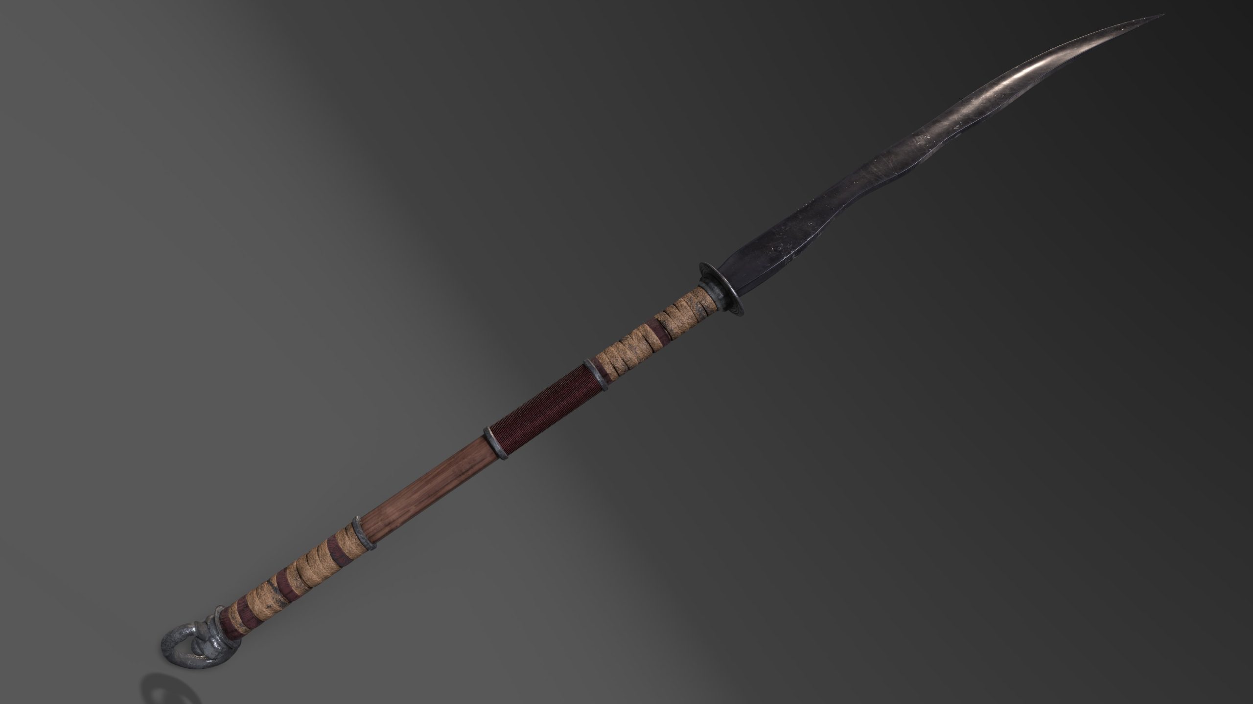
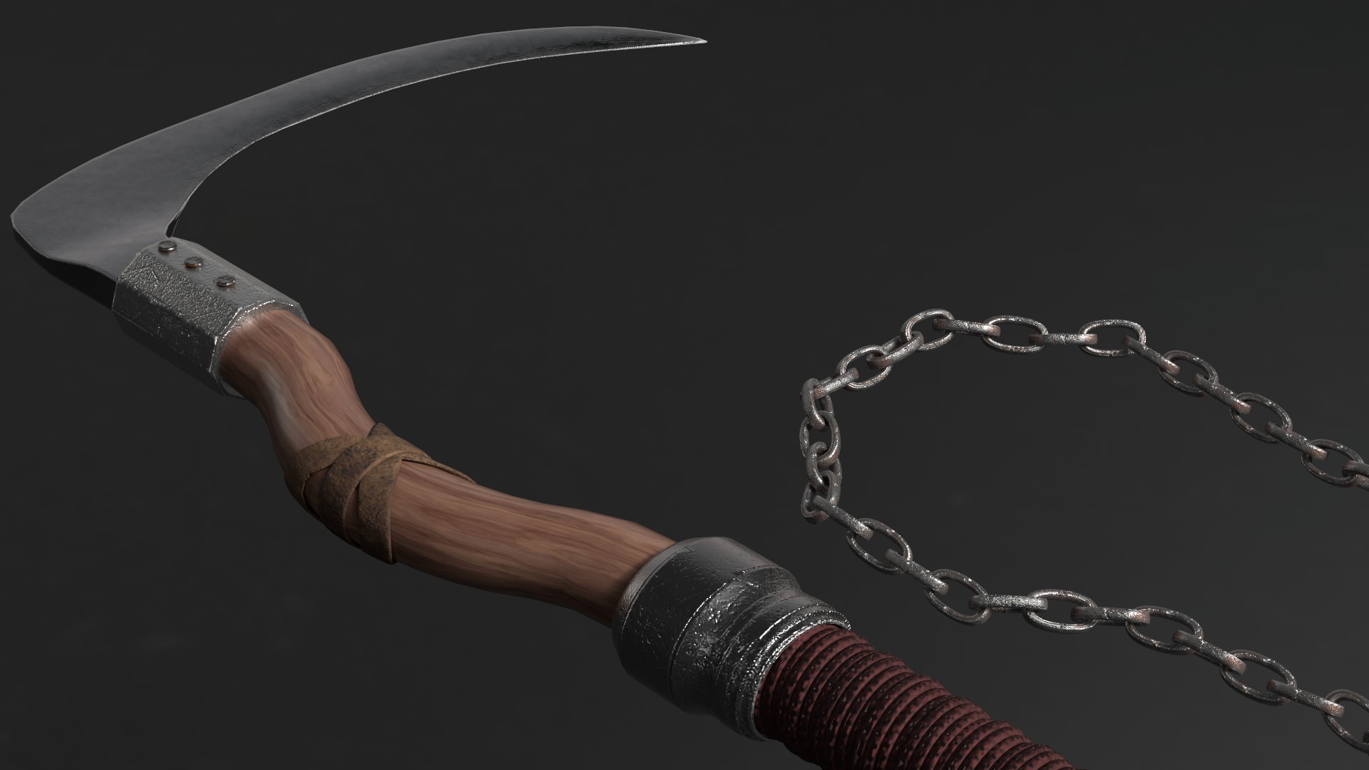
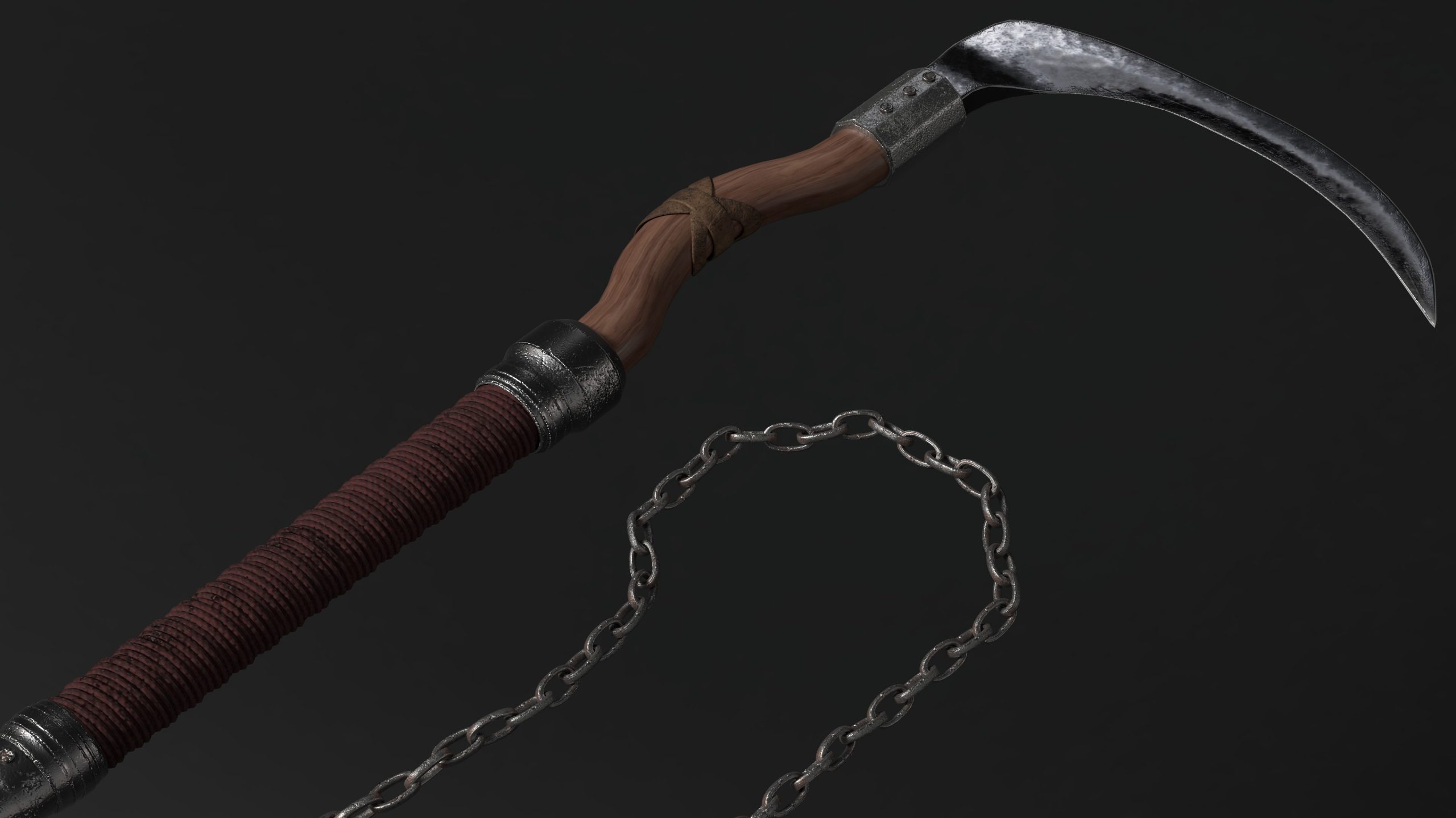
When creating the handle of the Naginata, I found that adding more subdivisions gave more creative control and lighter curves. This was tested through trial and error.
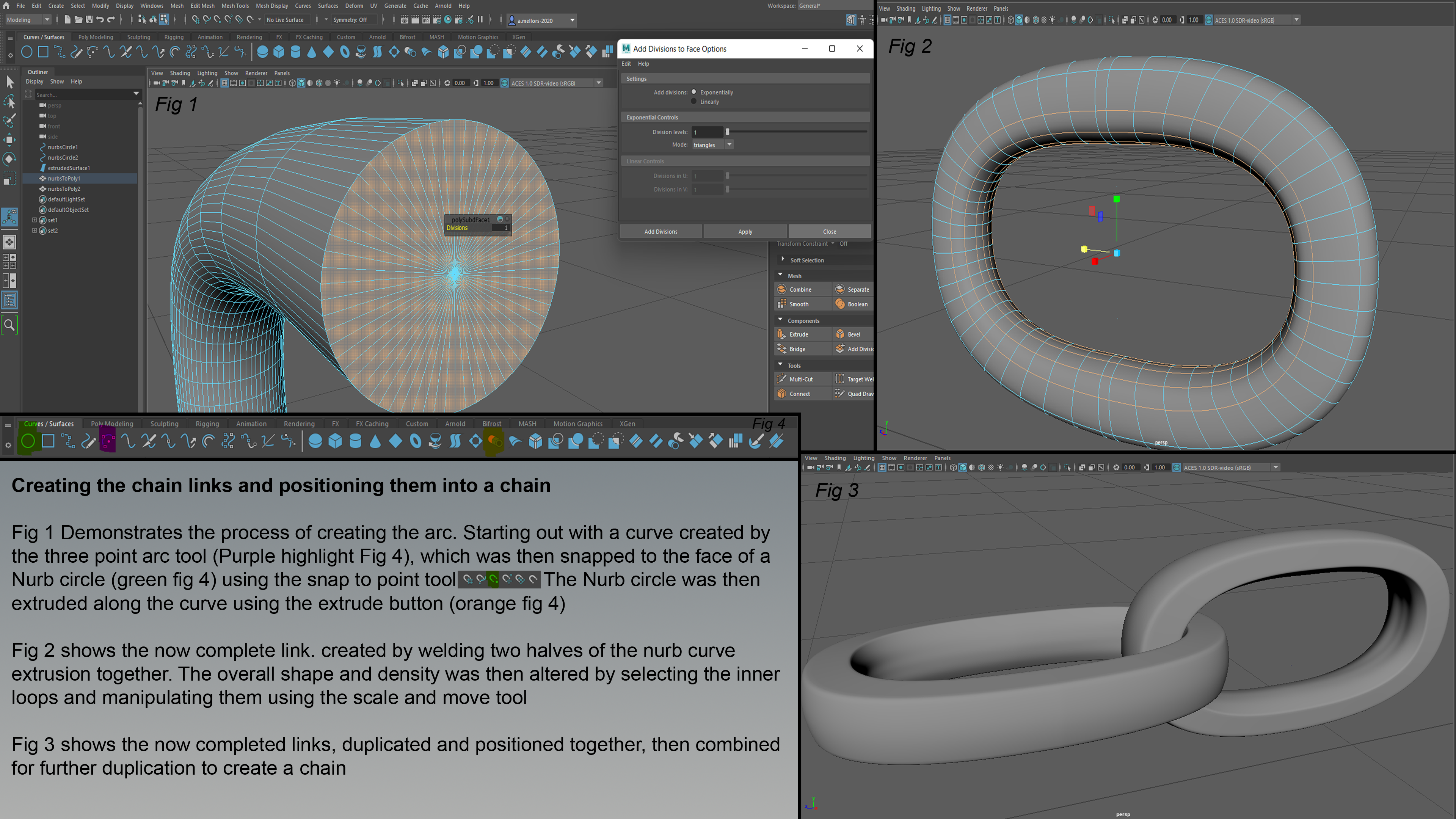
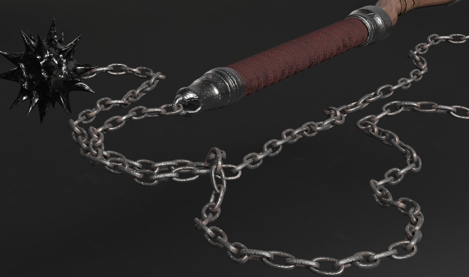
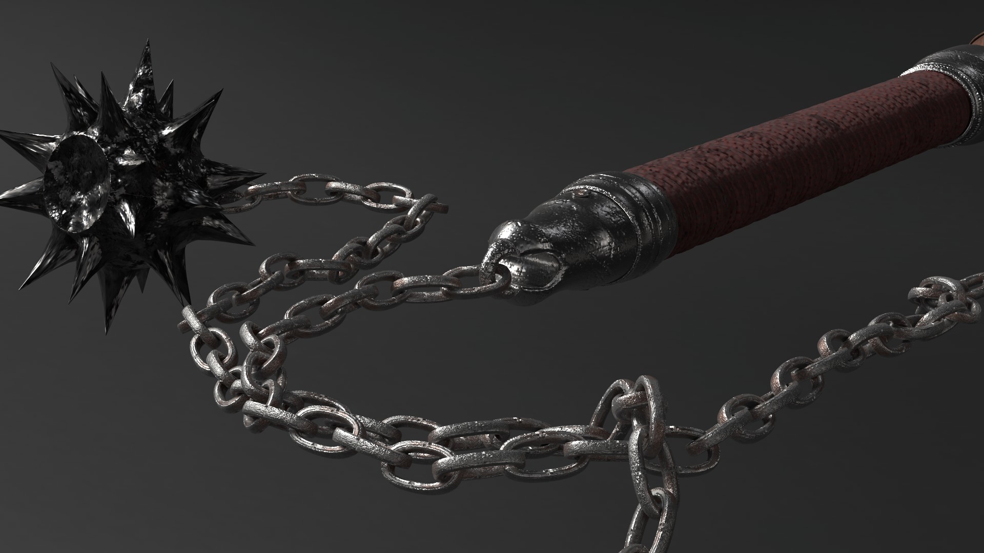
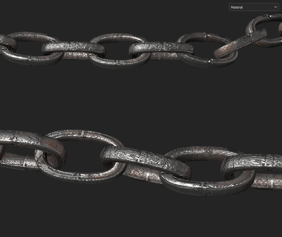
This image shows creating the chain links and positioning them into a chain. Fig. 1 demonstrates the process of creating the arc. Starting out with a curve, created by the three-point arc tool (Purple highlight Fig. 4), which was then snapped to the face of a Nurb circle (Green Fig. 4) using the snap to point tool, the Nurb circle was then extruded along the curve using the extrude button (Orange Fig. 4.) Fig. 2 then portrays the now complete link, created by welding two halves of the Nurb curve extrusion together. The overall shape and density were then altered by selecting the inner loops and manipulating then using the scale and move tool. Fig. 3 shows the now completed links, duplicated, and positioned together, then combined for further duplication to create a chain.
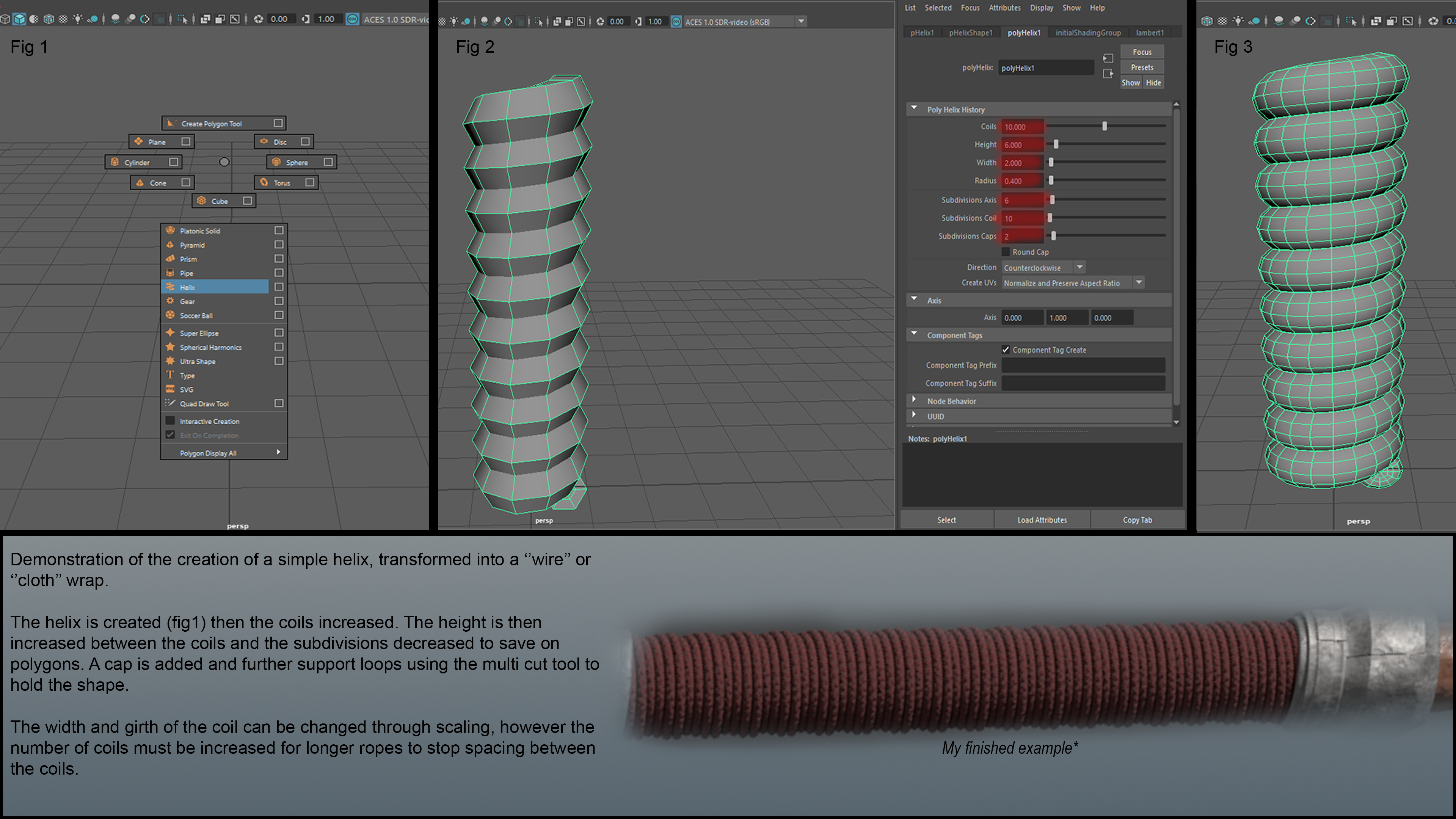
The image above is a demonstration of the creation of a simple helix, transformed into a ‘wire’ or ‘cloth’ wrap. The helix is created and then the coils increased. The height is then increased between the coils and the subdivisions decreased to save on polygons. A cap is added and further support loops are added using the multi cut tool, to hold the shape. The width and girth of the coil can be changed through scaling. However, the number of coils must be increased for longer ropes to stop spacing between the coils.
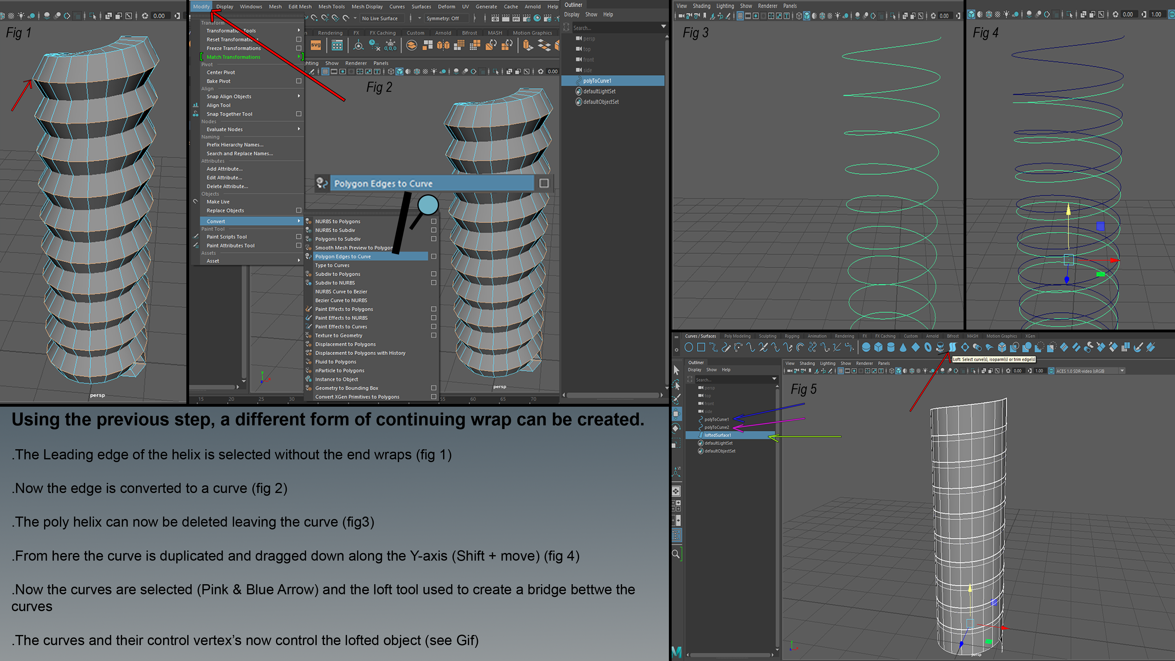
This image shows how a different form of continuing wrap can be created. In fig. 1, the leading edge of the helix is selected without the end wraps, it is then converted into a curve. The poly helix can now be deleted leaving the curve. From here, the curve is duplicated and dragged down along the Y-axis (Shift and Move). Now the curves are selected (Pink and Blue arrow), the loft tool is used to create a bridge between the curves. The curves and their control vertexes now control the lofted object (see GIF.)
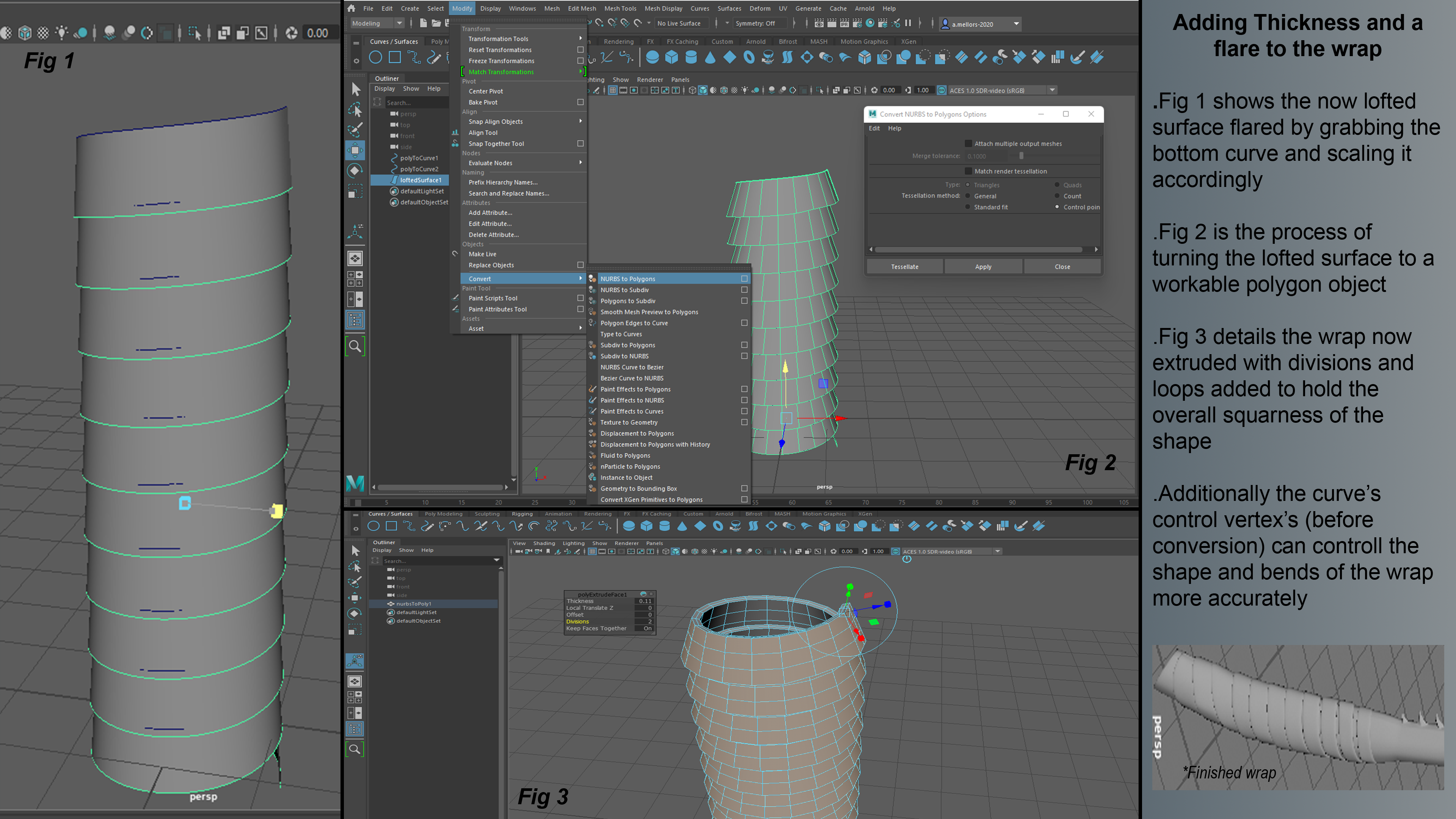
This image shows how to add thickness and flare to the wrap. With a lofted surface, it is flared by grabbing the bottom curve and scaling it accordingly. Fig. 2 shows the process of turning the lofted surface to a workable polygon object. Fig. 3 details the wrap now extruded with divisions and loops added to hold the overall squareness of the shape. Additionally, the curve’s control vertexes (before conversion) can control the shape and bends of the wrap more accurately.
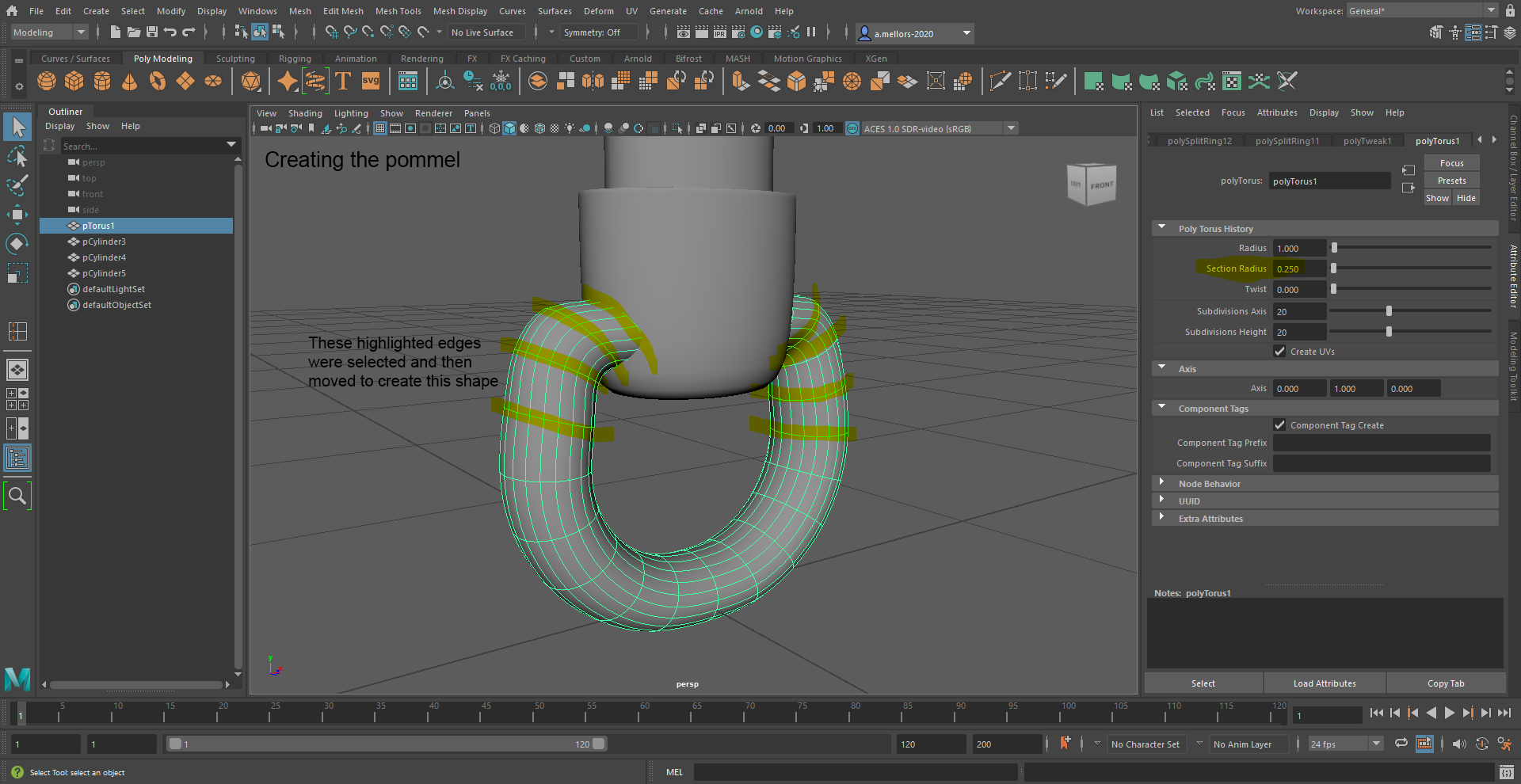
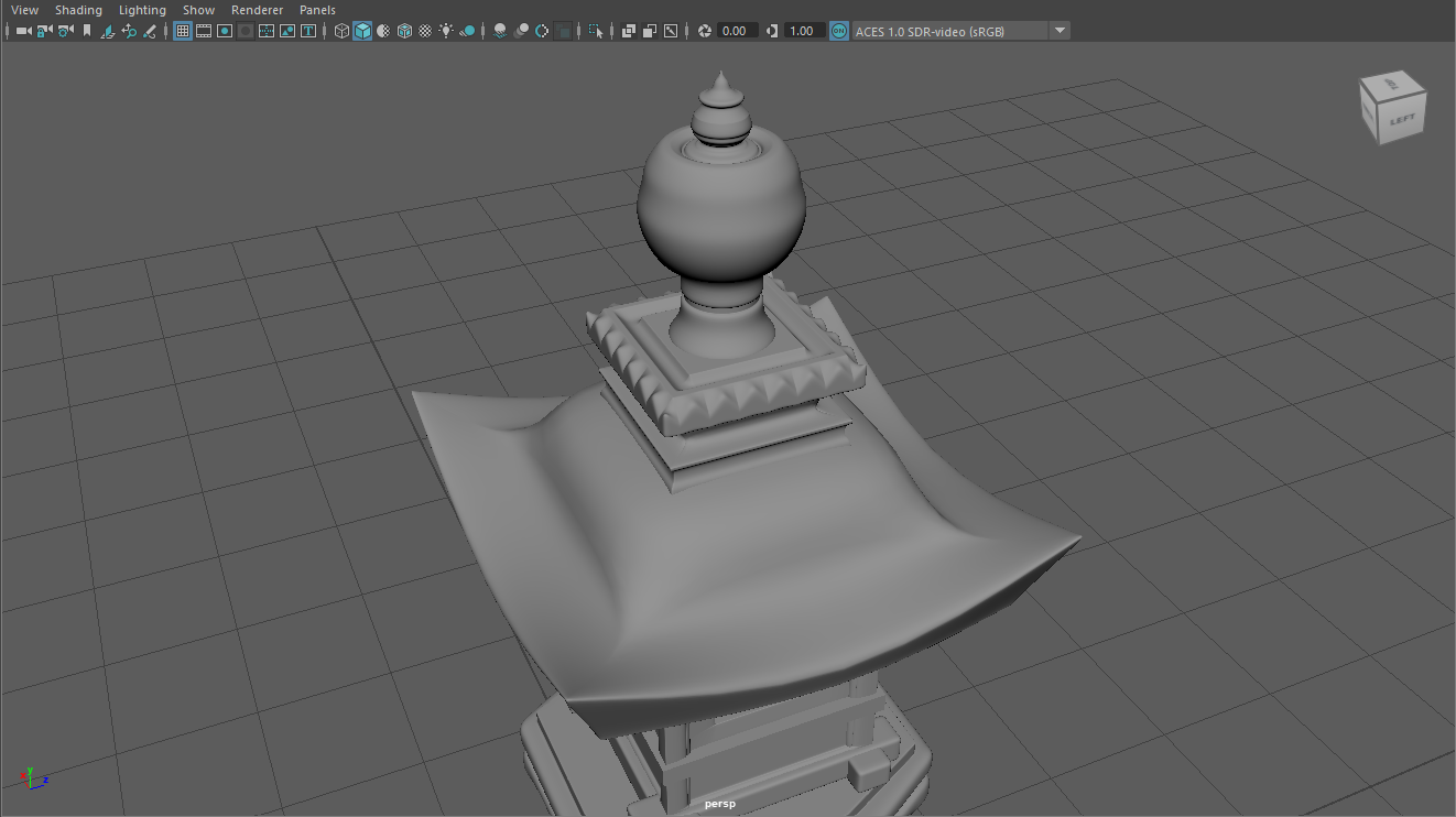
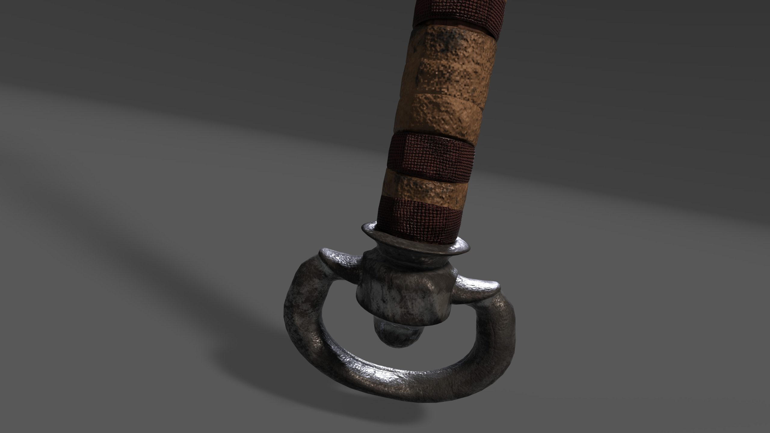
When creating the pommel, the highlighted edges were selected and then moved to create this shape.
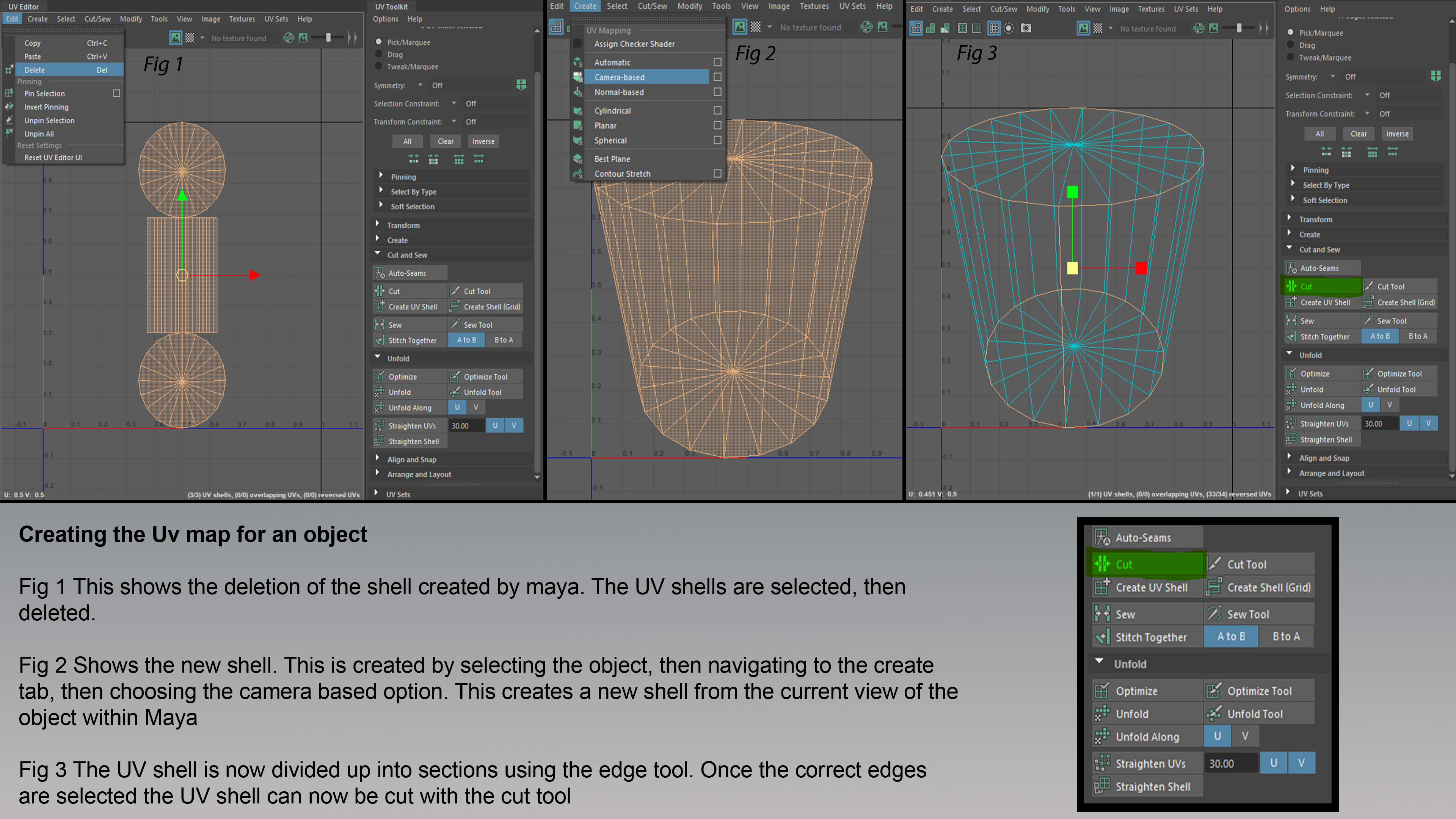
The image above shows creating the UV map for an object. Fig. 1 shows the deletion of the shell created by Maya. The UV shells are then selected, then deleted. Fig. 2 shows the new shell. This is created by selecting the object, then navigating to the create tab, then choosing the camera-based option. This creates a new shell from the current view of the object within Maya. In Fig. 3, the UV shell is now divided up into sections using the edge tool. Once the correct edges are selected, the UV shell can now be cut with the cut tool.
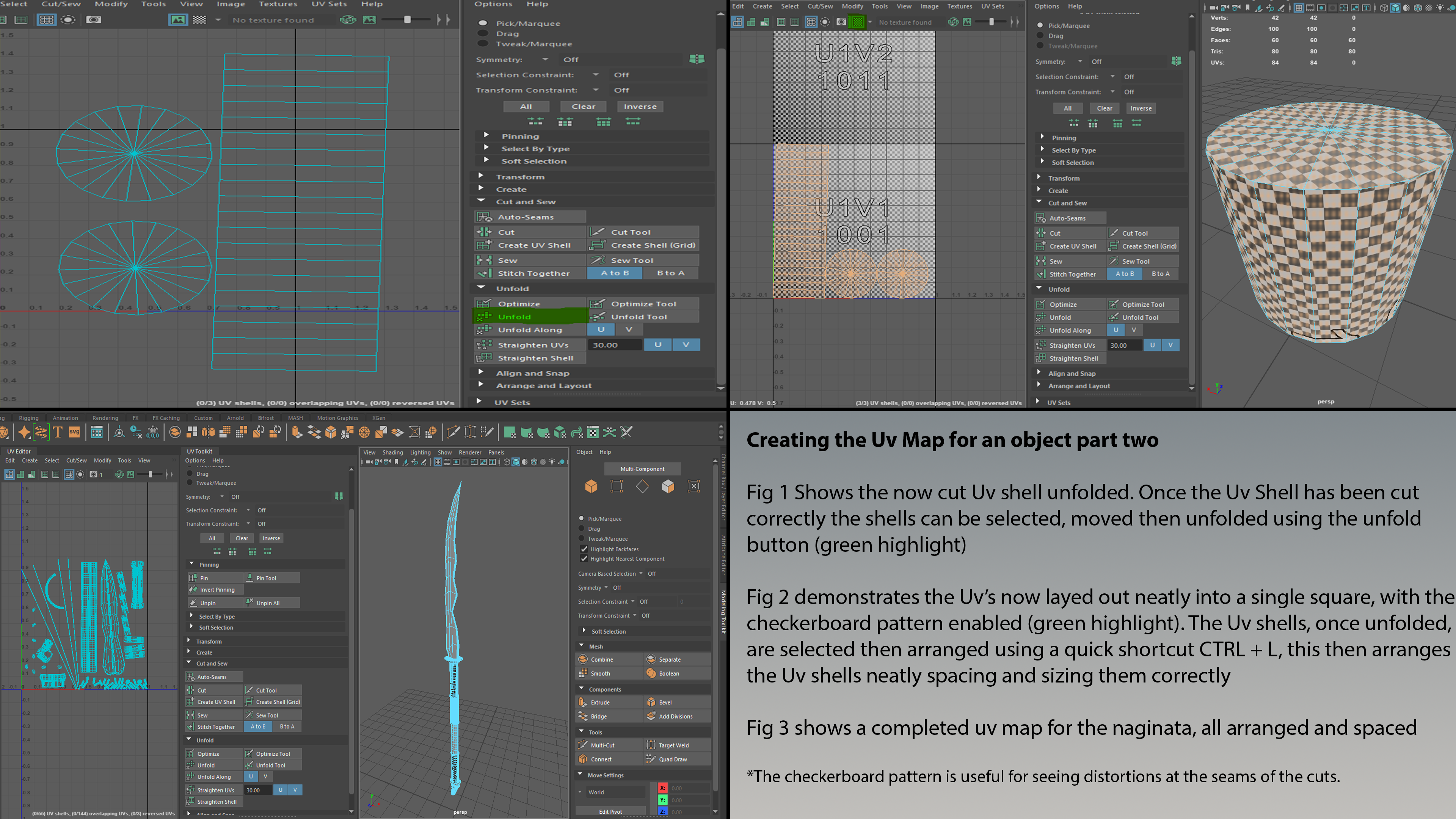
The image above shows creating the UV map for an object, part two. Fig. 1 shows the now cut UV shall unfolded. Once the UV shell has been cut correctly, the shells can be selected, moved and then unfolded using the unfold button (green highlight.) In Fig. 2, the UV is now laid out neatly into a single square, with the checkerboard pattern enabled (green highlight). The UV shells, once unfolded, are selected then arranged using a quick shortcut ’CTRL + L,’ this then arranges the UV shells, neatly spacing and sizing them correctly. Fig. 3 shows a completed UV map for the Naginata, all arranged and spaced. The checkerboard pattern is useful for seeing distortions at the seams of the cuts.
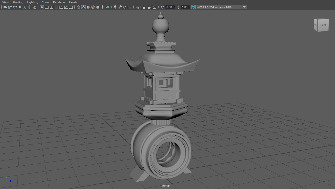
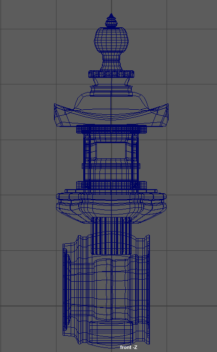
I used this knowledge to finally create my Toro Lantern.
How do the assets link to the environment location and theme?
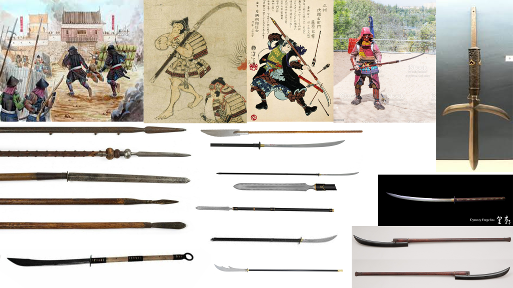
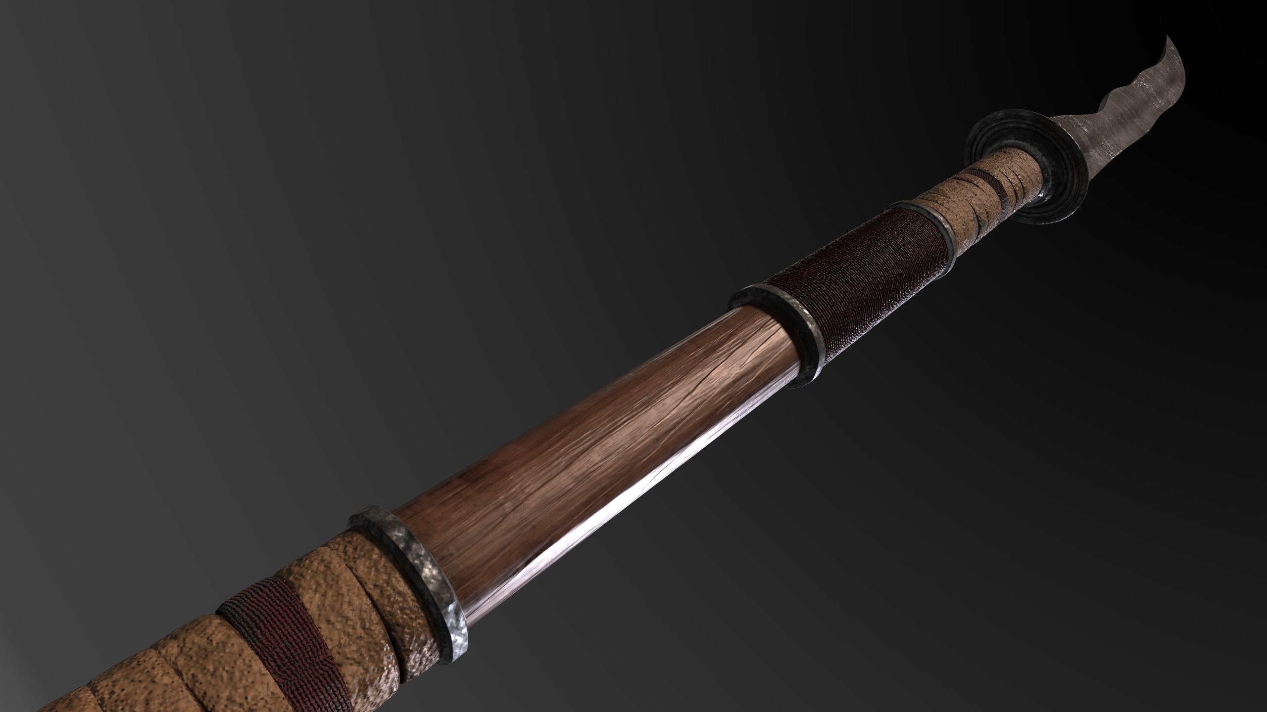
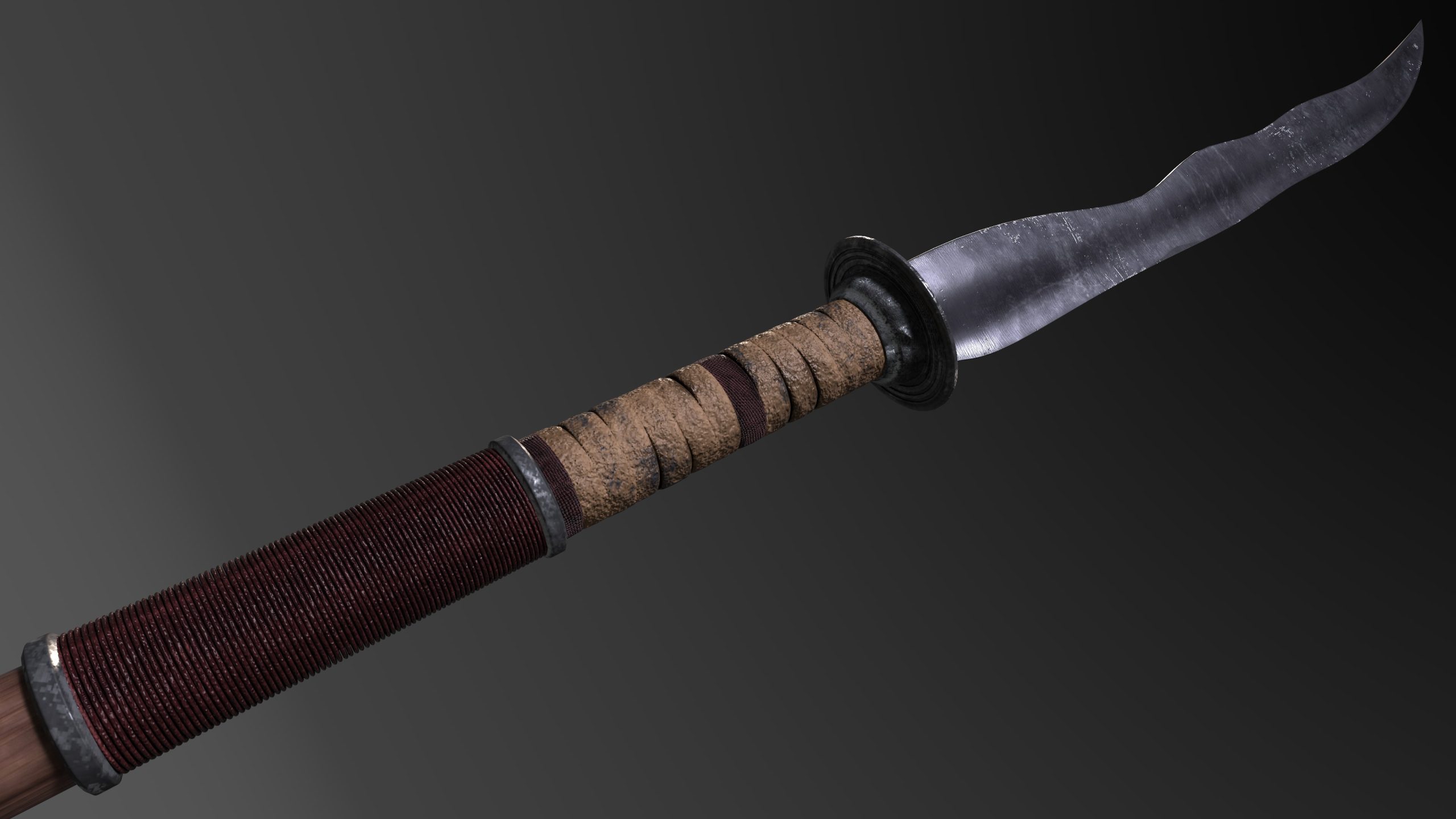
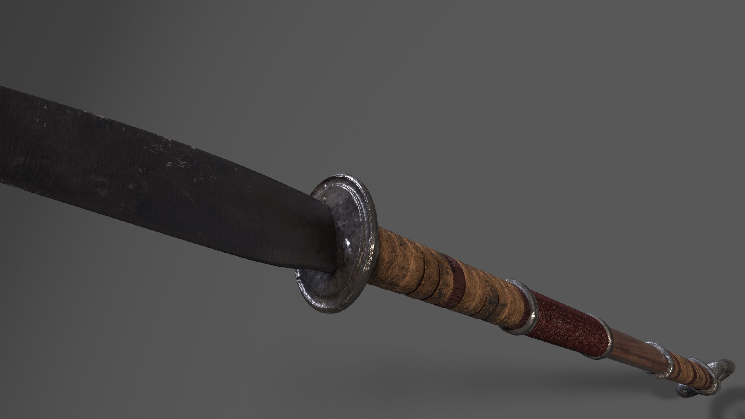
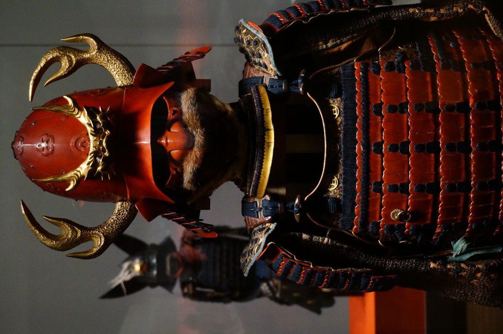
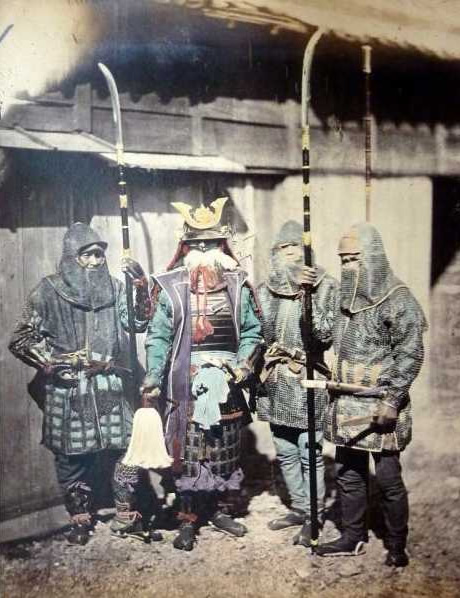
I used red regularly on the grips of the weapons as the traditional colour is red and white, this contrast made the weapon more Japanese, the inspiration for the shade of red came from the clothing Nobunaga wore during this period, he wore ‘a plum red silk garment next to his skin’ (Ōta, 2011:391).
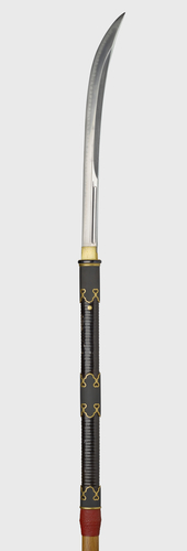
By SLIMHANNYA – Own work, CC BY-SA 4.0, https://commons.wikimedia.org/w/index.php?curid=92643632
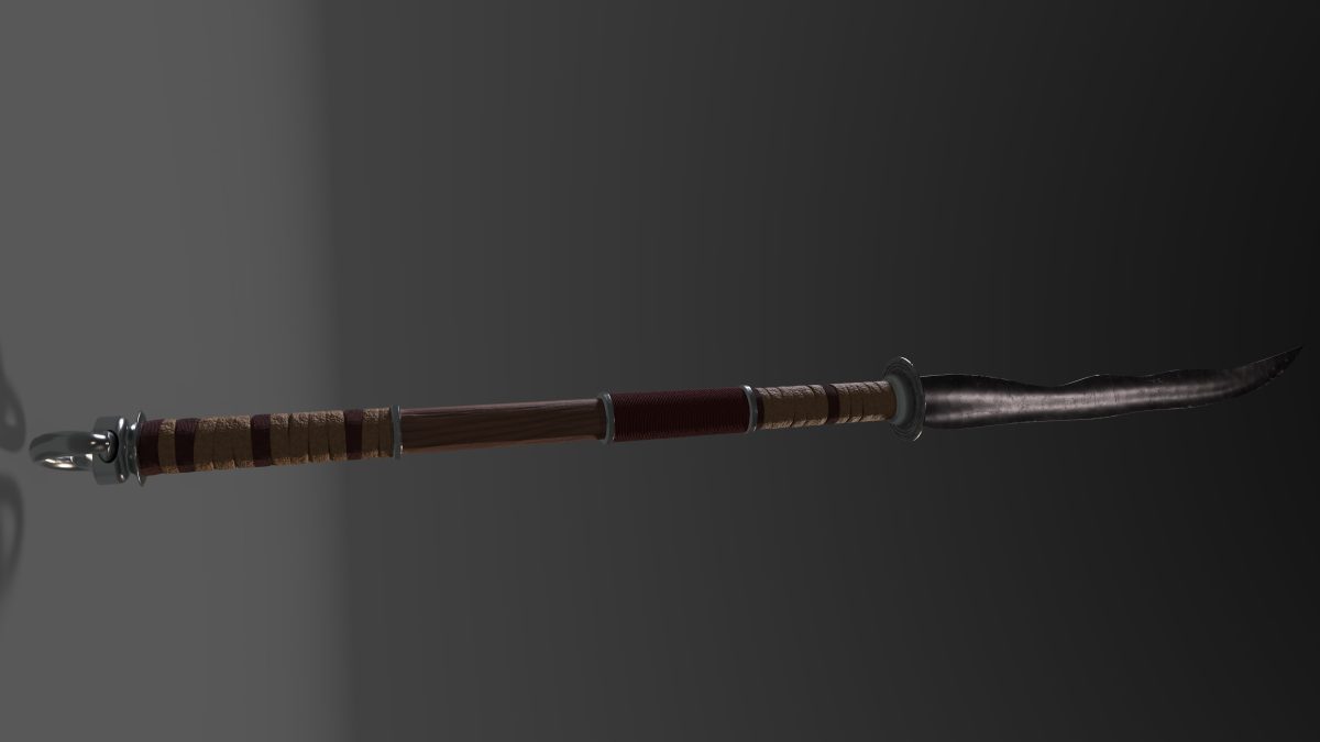
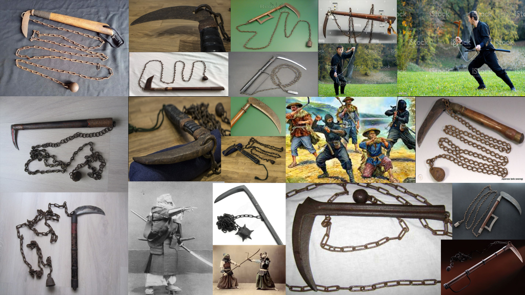
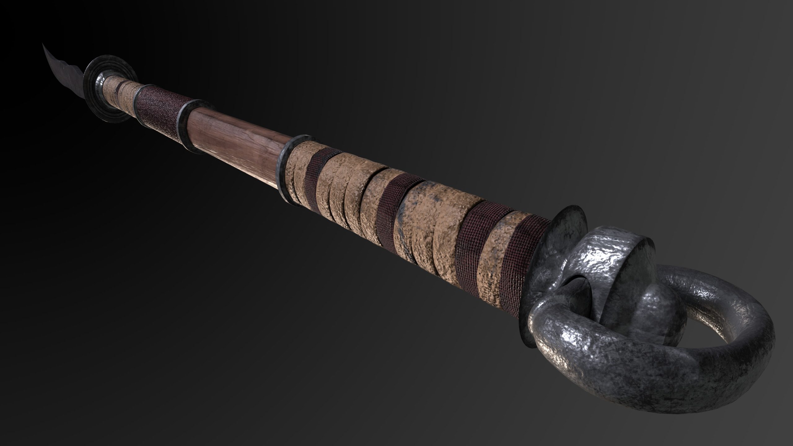
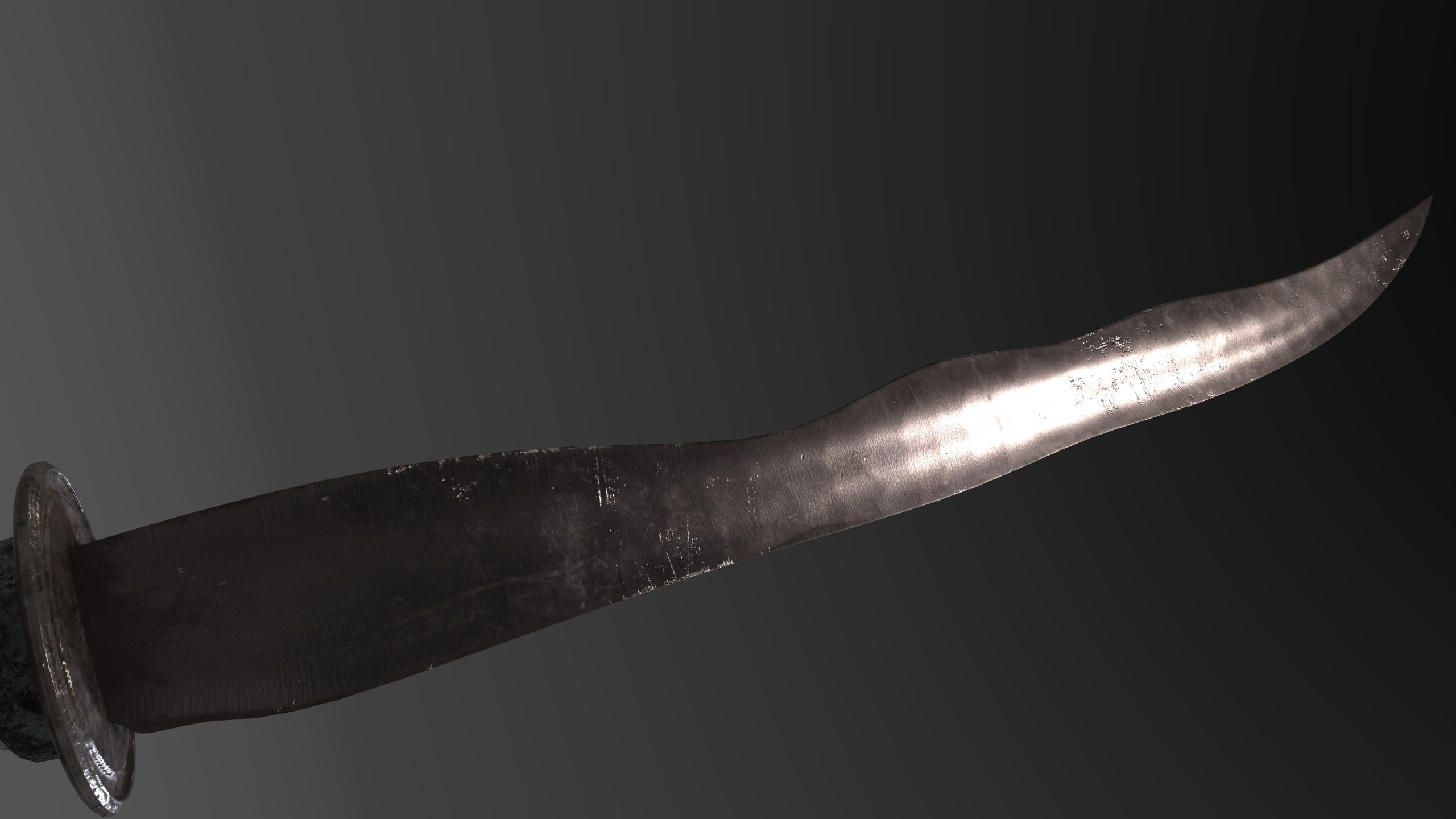
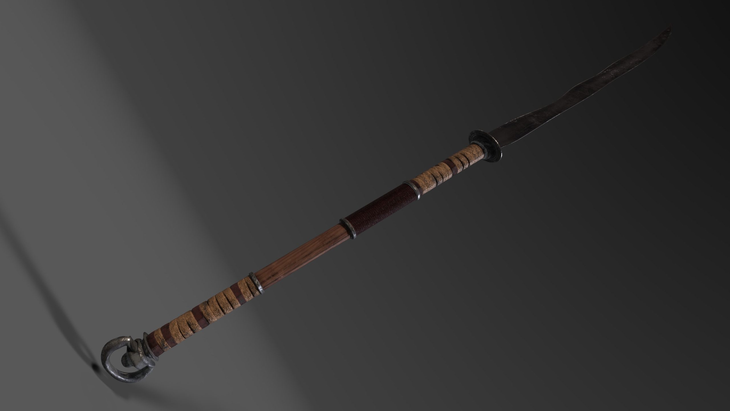
I took inspiration from Edo-period weaponry, which boasts smooth wooden shafts typically made from hard wood such as red or white oak. I used weapon shapes as seen in Chapter 2 of Demarco (2020). I have chosen white oak for both weapon designs as I wanted to be able to show damage and wear more easily in the design. The weapons were ‘tang-bladed with long-shafted handgrips’ (Demarco, 2020: Chapter 2). Japanese weapons tend to have ornate blade guards, handle collars and handle wraps – as family weaponry during this period tended to be an heirloom and passed through generations. I researched how the components of weapons, specifically Japanese, fit together and how they were overall forged. This knowledge gave me the ability to create weapons that were realistically possible. Certain components are made separately whereas some are made in one piece, therefore within the 3D programme I created them as such and could then portray this realistically in the asset design. Wraps on these weapons tended to be bonded to the blade and shaft with a pommel that was tempered around the shaft to hold the wraps in place. I have shown this by having the wrap disappear into the pommel and modelling the pommel with a slight lip.
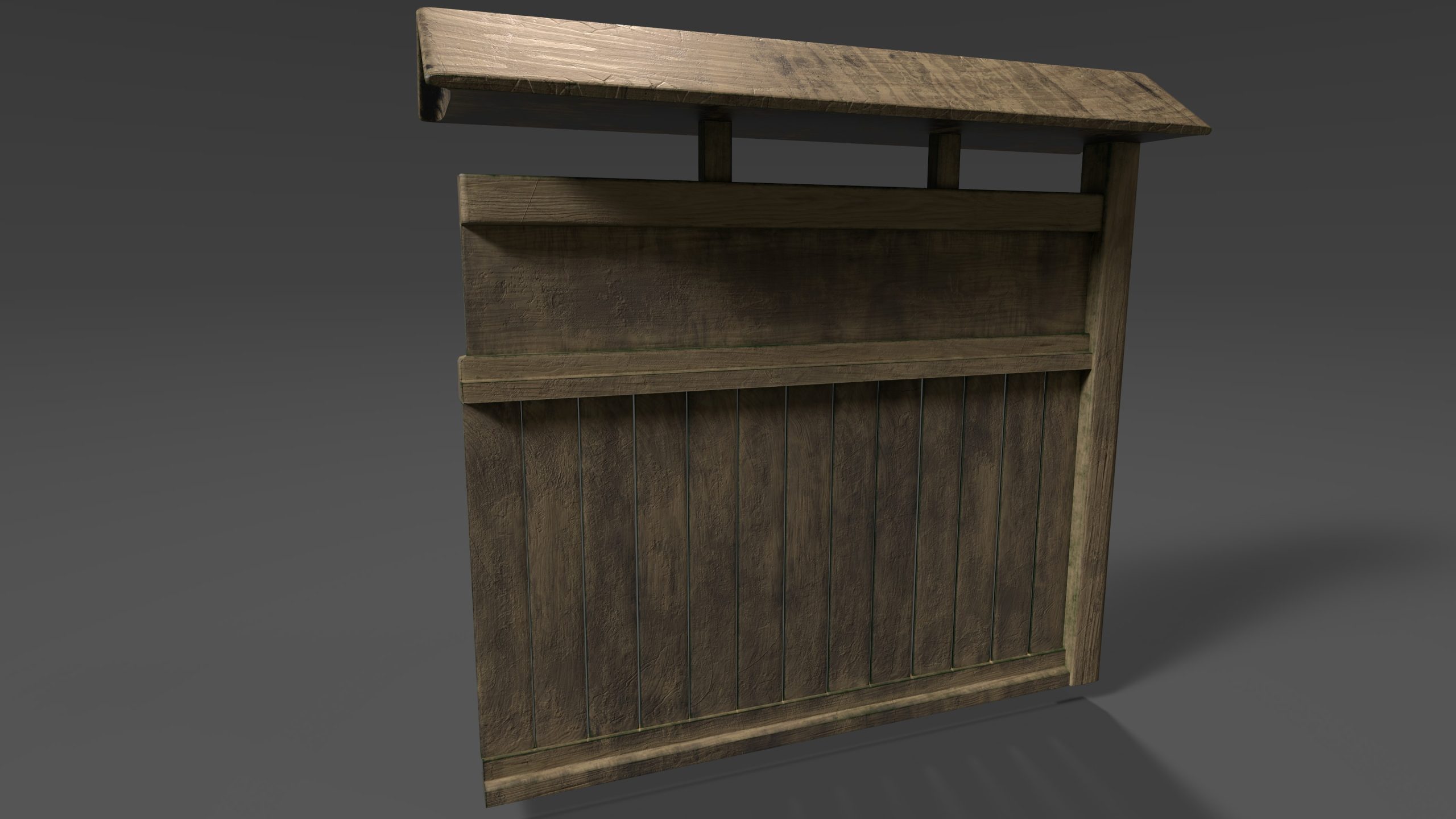
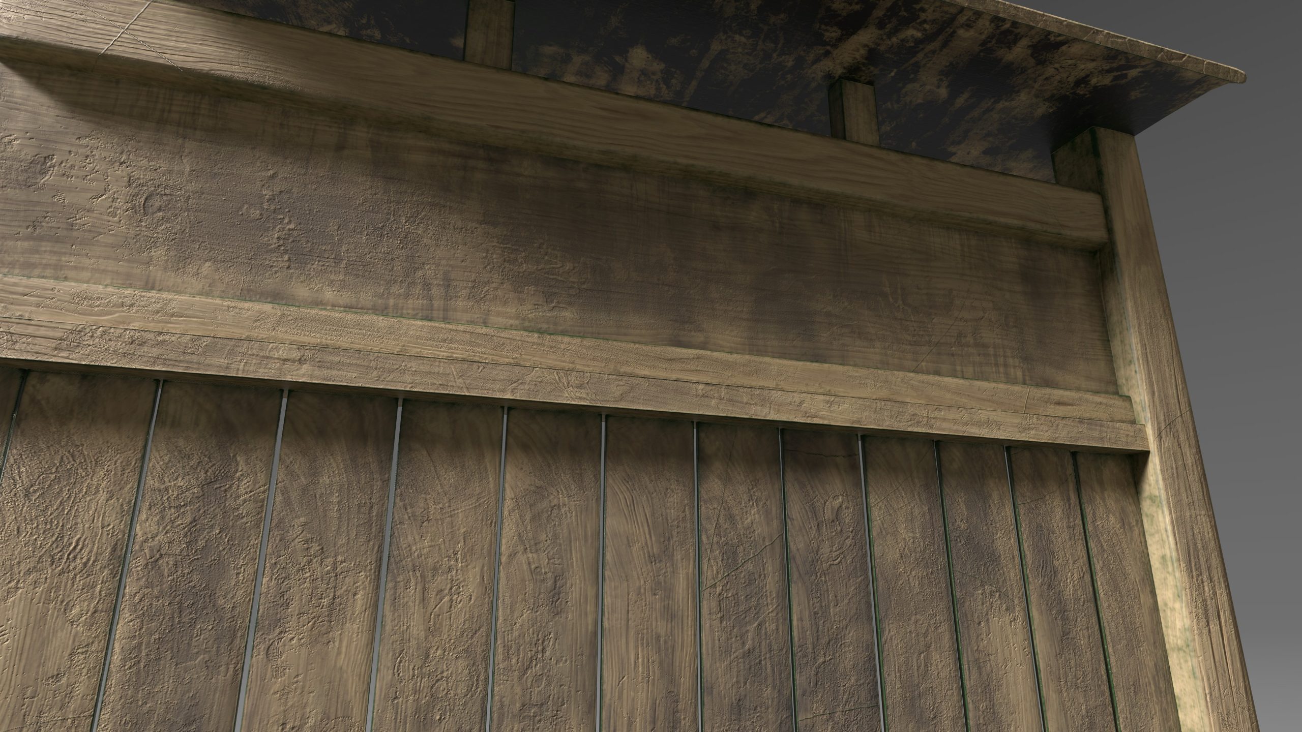
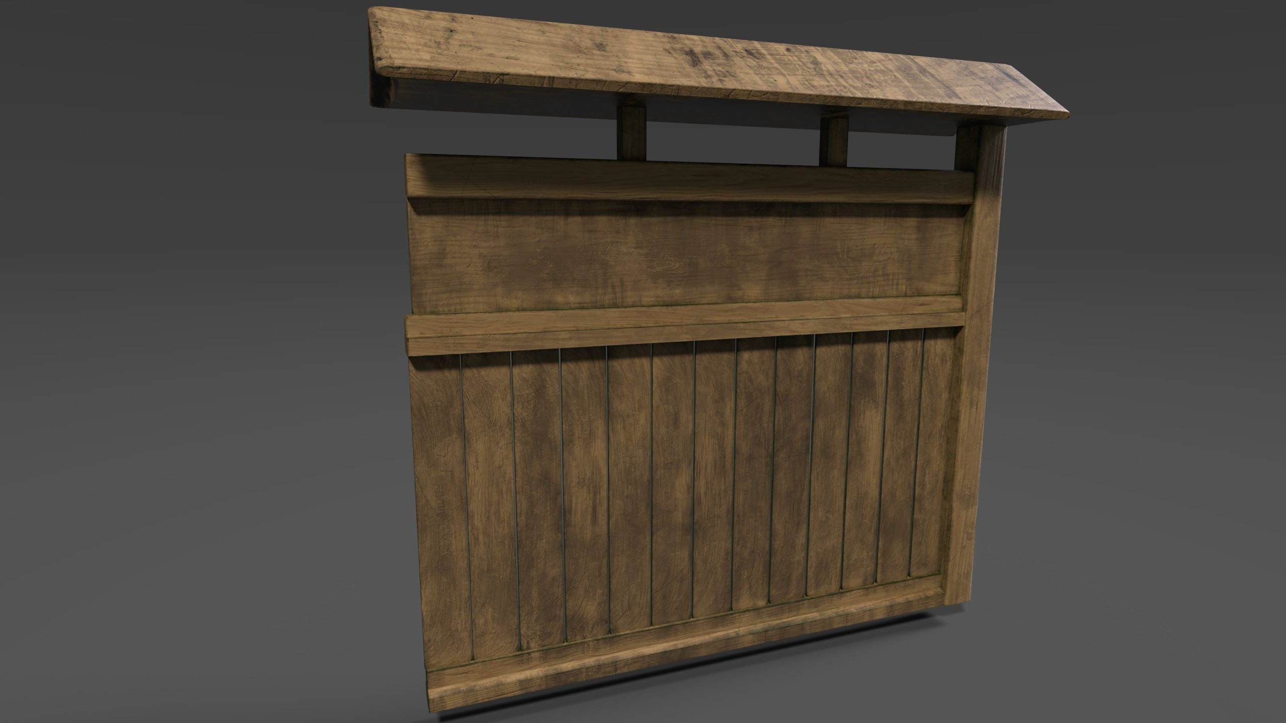
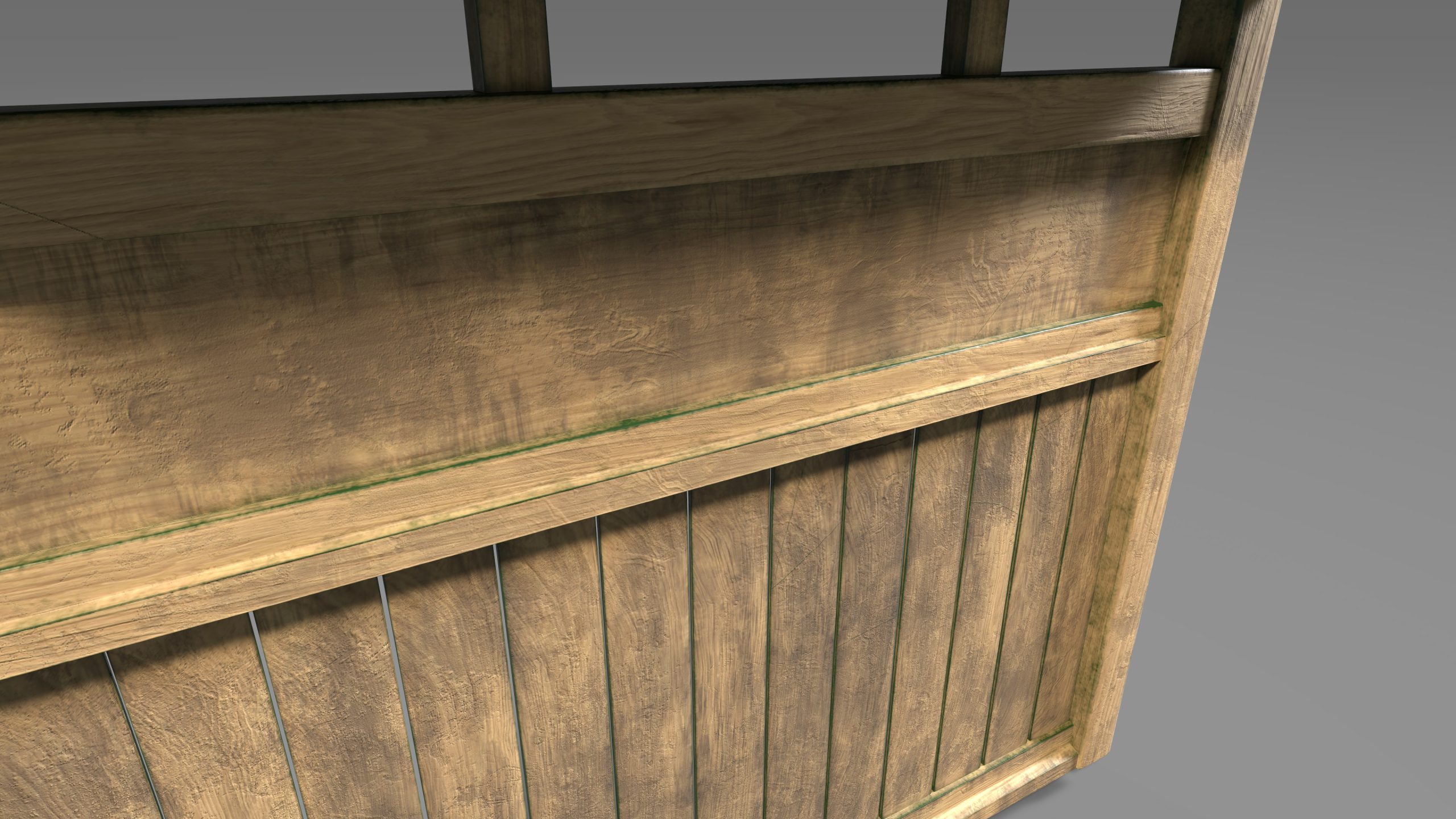
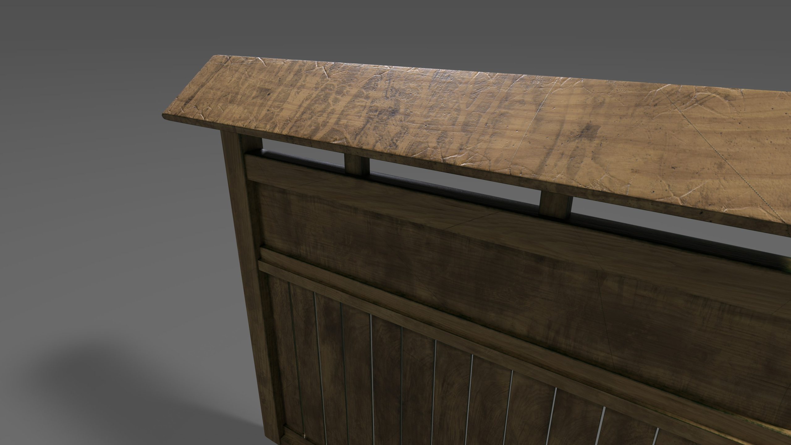
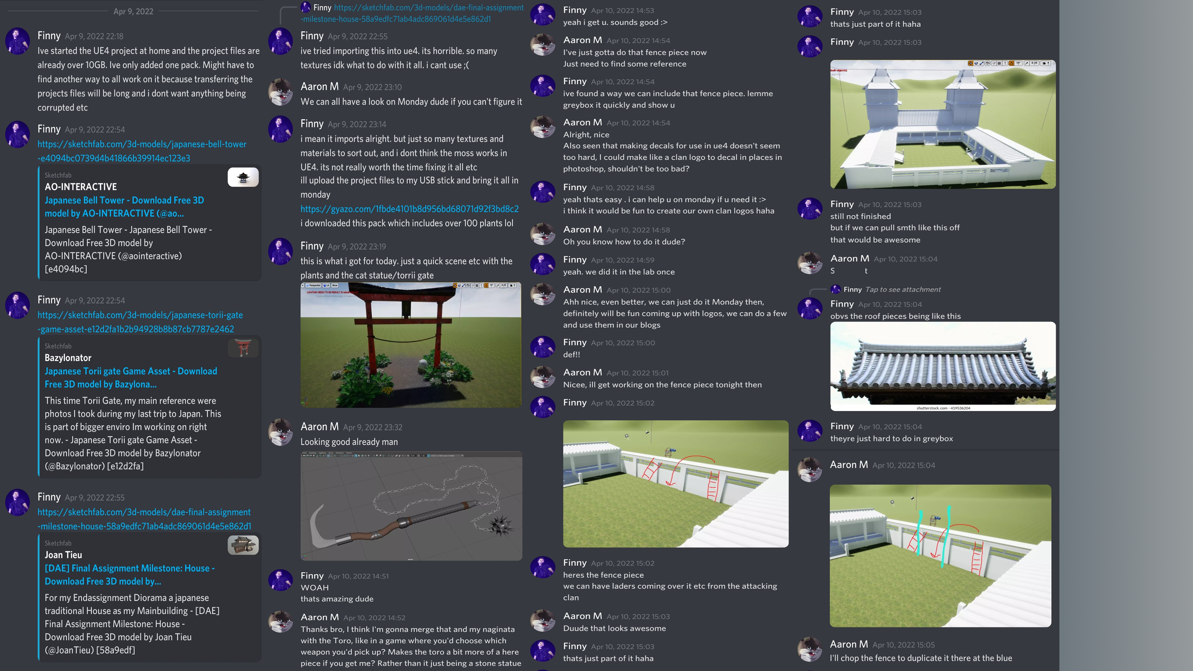
The circular base to the lantern is traditional to the theme, as it represents the cyclical form of nature. The lantern features docks and indentations which portray the intricacies of Japanese culture. The lantern itself, can be found within a covered wood section of the lantern. The lantern is metaphorical for the burning during battle which Nobunaga was known for as seen in the Battle of Mikatagahara where he set fire to the city environs (Ōta, 2011:7). The shape of the roof of the lantern has cornered crests to collect water, this is imperative to the theme as it explicitly links to nature and the ‘waterfall’ type motion of water off the lantern.
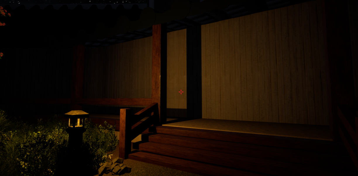
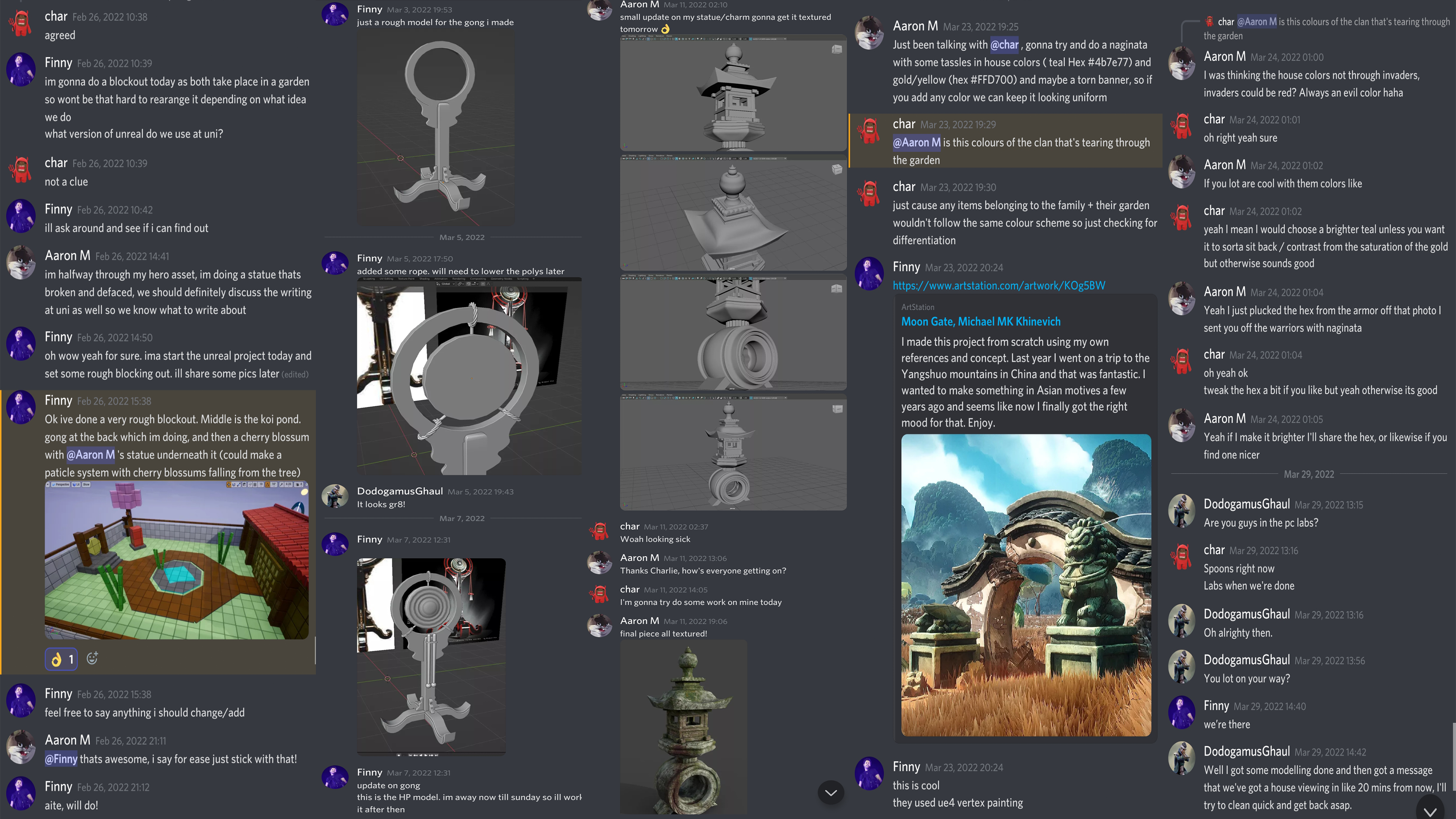
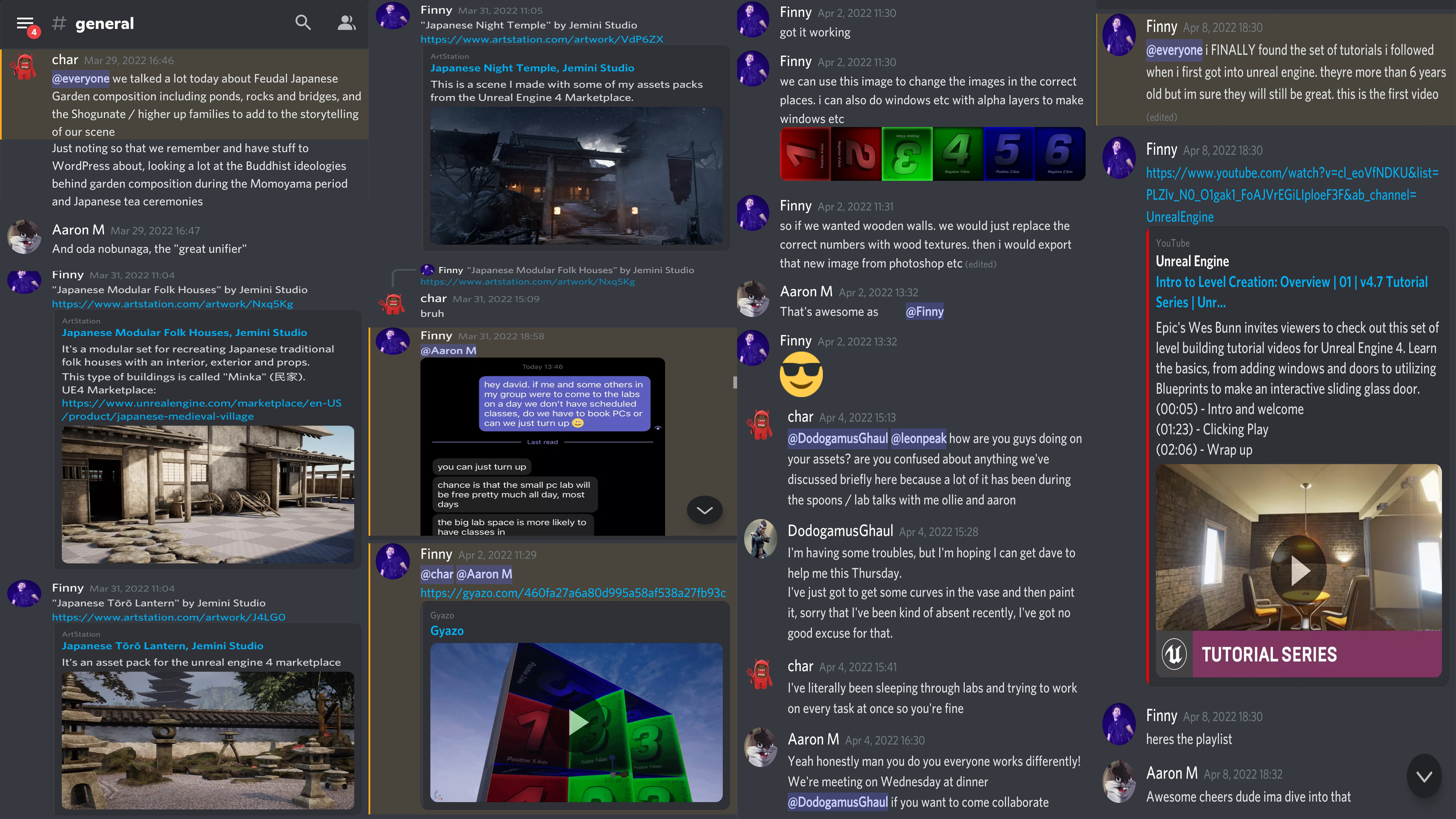
The story for the scene begins in Edo-period feudal Japan. It is a time of war and cultural change. The warlord, Oda Nobunaga and his clan, are sweeping through the land gathering allies and killing enemies. They are in search of artefacts which may strengthen the leader’s claim to the Shogunate. Throughout this journey, Nobunaga comes across a noble’s house, belonging to the Ouriki clan. The household are not supporters of the warlord and so a battle ensues. The gong is sounded (gong created by Oliver Webb) as an alert to the attack and the walls (created by Aaron Mellors) are breached and burnt. The house is then ransacked and the garden destroyed in search of a cursed vase (created by Joel Easters.) Once the vase is found, it releases a demon. The only way to stop this demon is from the mythical water produced by the bamboo water fountain (created by Charlie Cottrell) but before anyone can do this the demon kills everyone in the immediate vicinity and inhabits the Toro lantern (Created by Aaron Mellors) in the gravel garden. It does this to spread its dark light. A fight ensues between two great warriors to try and claim the lantern and its power, however both warriors kill one another. They disappear into the lantern leaving only their weapons (Created by Aaron Mellors) and blood behind, these can be found lying on the ground. The lantern represents links with the dead, in the summer ‘Buddhist’s celebrate the festival of the Dead’ to pay homage to those who have deceased’ (Baroni, 2002:90). The blood spattered across the lantern is therefore symbolic to this link between peace and death. For inspiration to the weaponry, I took inspirations from drawings of feudal characters and read about the uprising of militia during this time (Ratti and Westbrook, 1973:53). This had an impact and supported the group when trying to visualise the story before creating the assets.
Our group has been meeting for 3-hour sessions at university in which we have discussed asset designs, period choice, architectural designs, scenic lighting, the story and traditional Japanese garden items – which could be considered hero assets. We discussed the history behind the Edo-period and linked this to the socio-economic period, we concluded that a war could be pinpointed down to a scene effectively and this is what we have tried to create. Once we had each decided which assets we would like to create, we kept each other updated regularly to ensure our ideas were unique.
References:
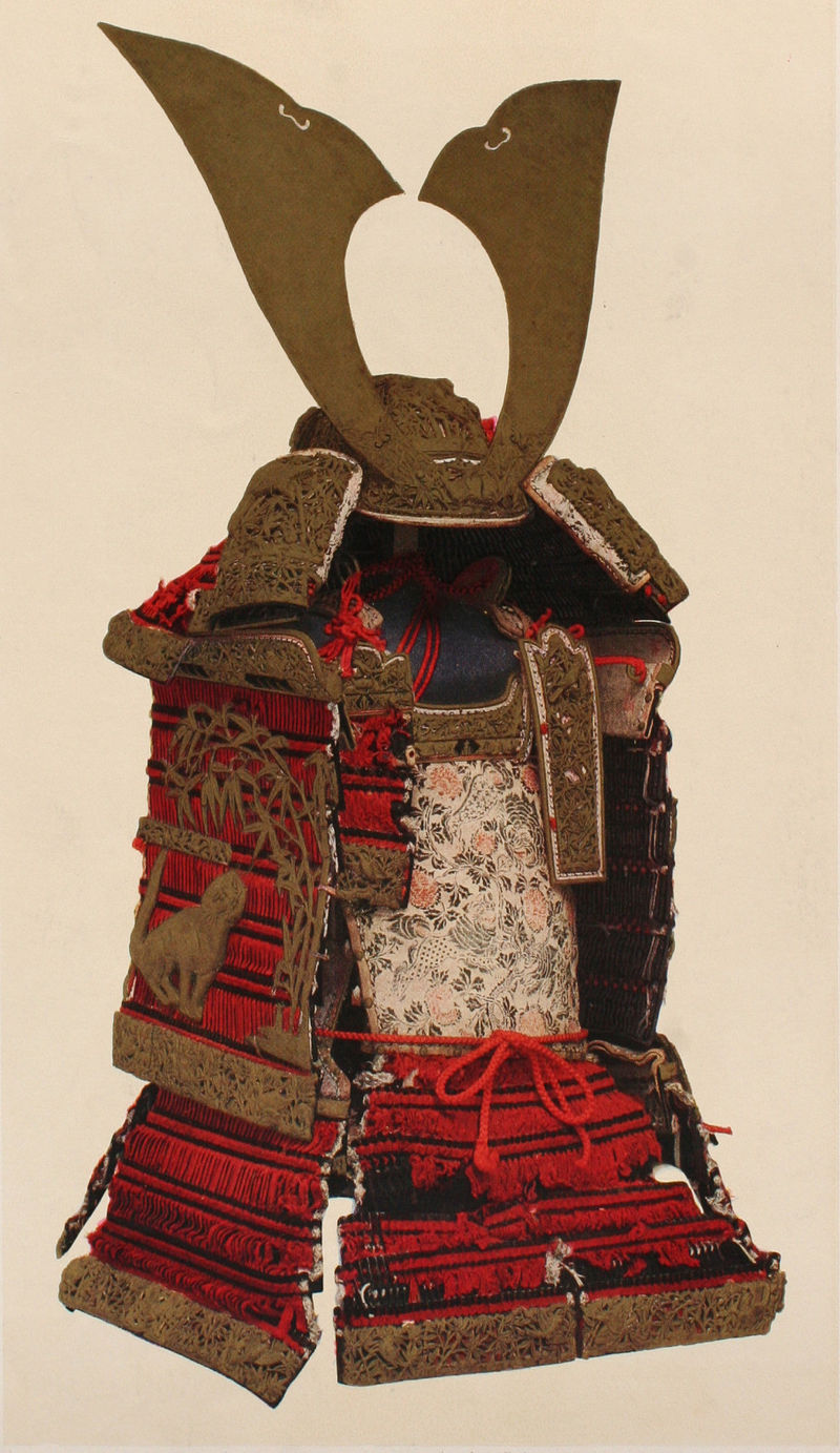
By Association of Cultural Properties – Portfolio of National tresures Volume 1st, Association of Cultural Properties, Tokyo, 1952-03-30, Public Domain, https://commons.wikimedia.org/w/index.php?curid=15404803
Baroni, H. J. Ph. D. (2002) The Illustrated Encyclopedia of Zen Buddhism. Published by Rosen Publishing Group.
Demarco, M. (2020) Japanese Weapons – An Anthology. Published via Media Publishing.
Katana Swords. (2020) Samurai Weapons: Naginata. Published Online. https://katanaswords.info/samurai/naginata/
McMullin, N. (2014) Buddhism and the State in Sixteenth Century Japan. Published by Princeton University Press.
Ōta, G. (2011) The Chronicle of Lord Nobunaga. Translated and edited by J. S. A. Elisonas and J. P. Lamers.
Ratti, O. and Westbrook, A. (1973) Secrets of the Samurai: The Martial Arts of Feudal Japan. Published by Tuttle Publishing, an imprint of Periplus Editions (HK) Ltd.
Royal Collection Trust. (2020) Polearm (naginata) 1850-60. FUJIWARA YASUTSUGU (ACTIVE 1860). https://www.rct.uk/collection/71616